Chemical plant waste gas treatment pipeline sealing treatment system

A technology for exhaust gas treatment and pipeline sealing, which is applied in the direction of engine sealing, pipe components, pipes/pipe joints/fittings, etc., which can solve the problems of high safety measures, long time consumption, aging of sealing strips, etc.

Active Publication Date: 2020-10-20
济源市恒顺新材料有限公司
View PDF8 Cites 1 Cited by
  • Summary
  • Abstract
  • Description
  • Claims
  • Application Information

AI Technical Summary

Problems solved by technology

[0004] (1) The pipe replacement repair method can solve all the problems existing in the repair section at one time, but there are certain safety and environmental risks in the pipe replacement repair, which requires high safety measures for construction operations
In addition, the construction of pipe replacement requires large-scale equipment and excellent welding technicians, which takes a long time and requires high maintenance costs
[0005] (2) The surfacing welding repair method does not need to close the pipeline during construction, which is more convenient than the pipe replacement repair method, but there are risks in welding operations on the running pipeline, which may cause the pipe wall to burn through and burst
Once the pipe at the welded part is corroded and perforated, a pressurized cavity will be formed between the outer wall of the original pipe and the reinforcing steel plate. Due to the lack of penetration, the weld is easily pulled apart, causing greater losses
[0006] (3) The pipeline repairer is composed of two semi-annular structures. During construction, the two semi-annular structures are closely attached to the outer wall of the pipeline, and then the two semi-annular structures can be connected by bolts and other connecting parts without closing the pipeline. And there is no risk of damage to the pipe wall during construction, but because the two half-rings are connected by a sealing strip, the sealing strip will age after long-term use, and the sealing performance will be reduced. It is necessary to remove the repair device from the outer wall of the pipe before repairing it. Seal strips for replacement

Method used


Image

  • Chemical plant waste gas treatment pipeline sealing treatment system
  • Chemical plant waste gas treatment pipeline sealing treatment system
  • Chemical plant waste gas treatment pipeline sealing treatment system

Examples


Embodiment Construction

[0027] The embodiments of the present invention will be described in detail below with reference to the accompanying drawings, but the present invention can be implemented in many different ways defined and covered by the claims.

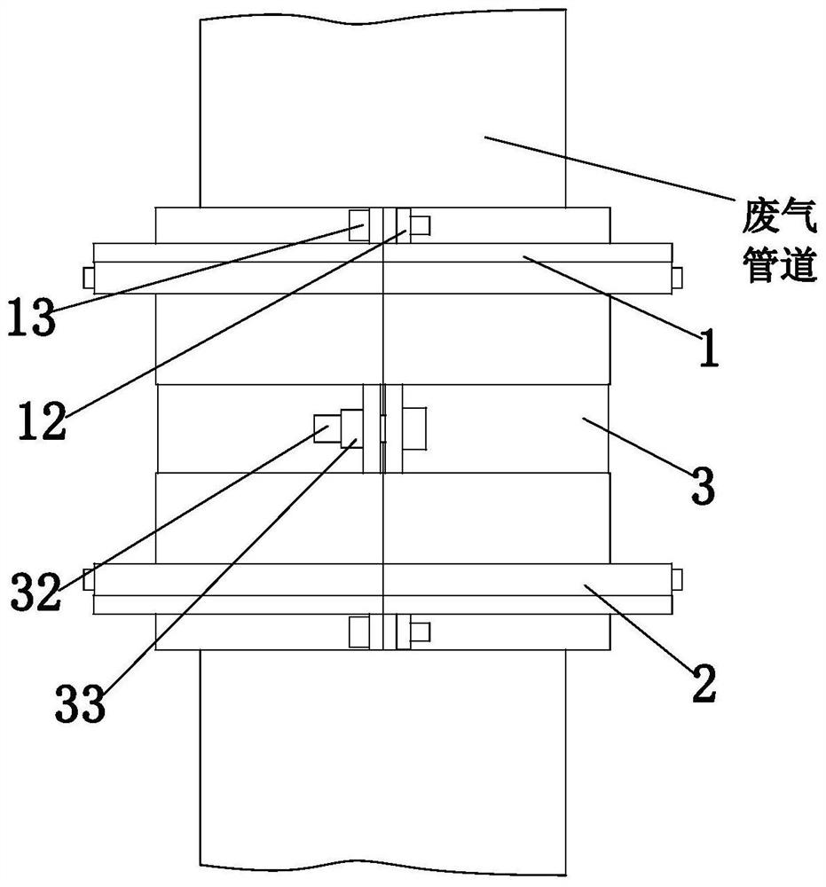
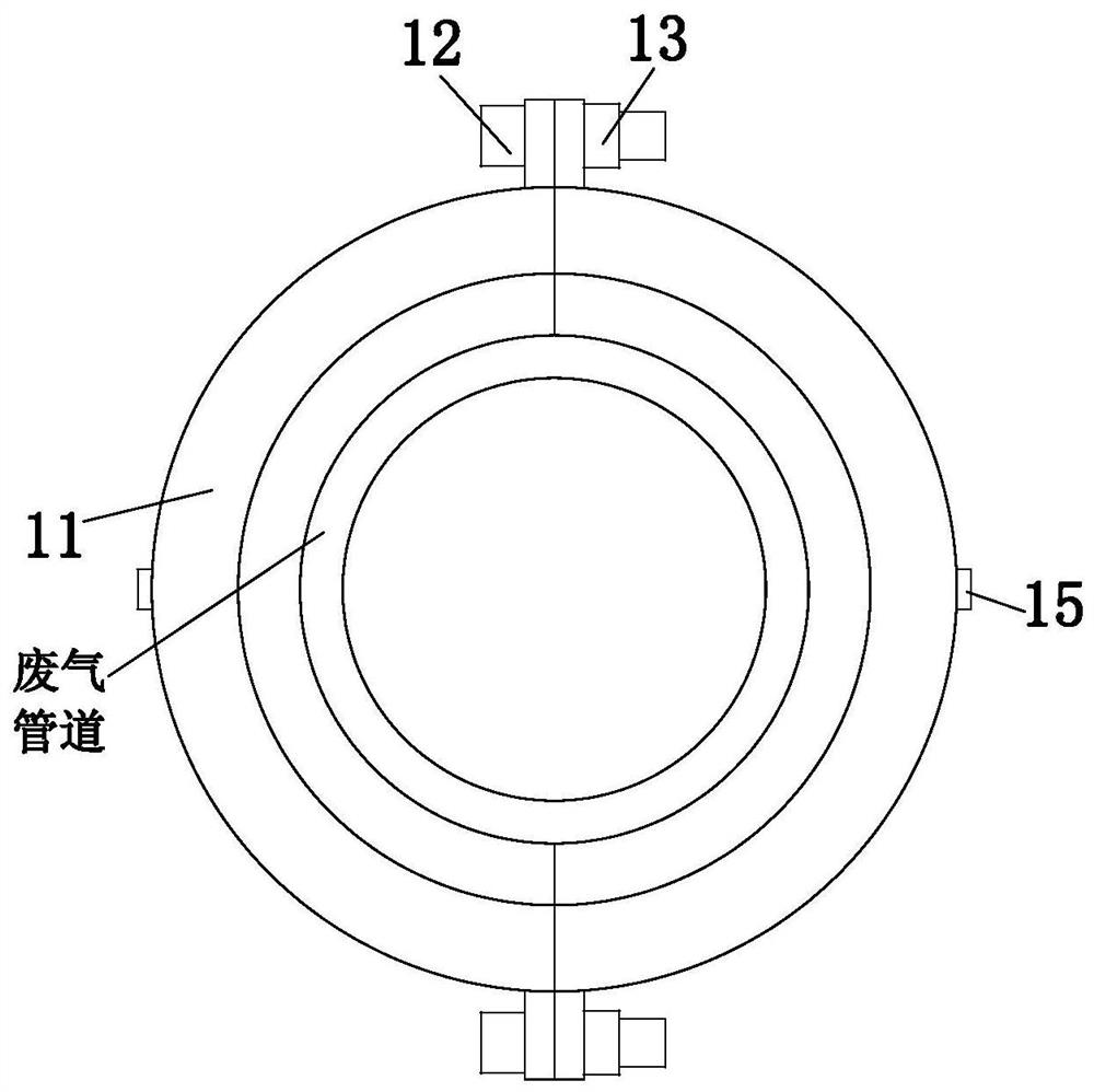
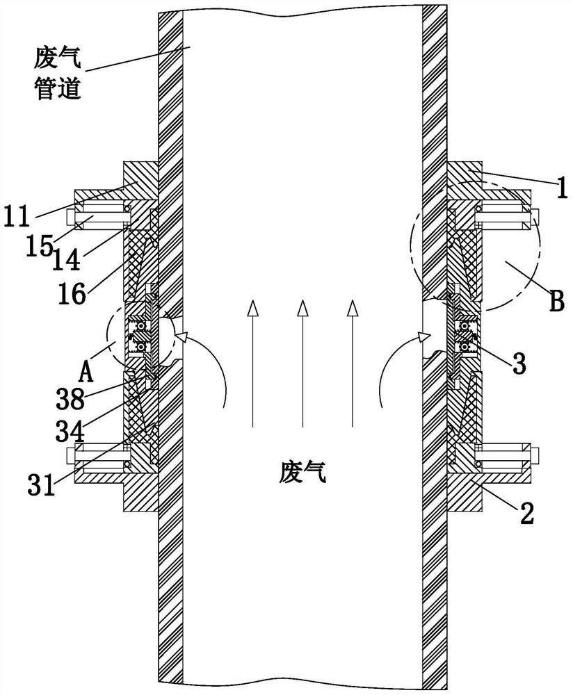
[0028] Such as Figure 1 to Figure 6 As shown, a chemical plant exhaust gas treatment pipeline sealing treatment system includes an upper locking mechanism 1, a lower locking mechanism 2 and a repairing mechanism 3. The upper locking mechanism 1 and the lower locking mechanism 2 are symmetrically arranged up and down, and the locking A repair mechanism 3 is connected between the tightening mechanism 1 and the lower locking mechanism 2; wherein:

[0029] The repair mechanism 3 includes a repair half ring 31, a connecting bolt 32, a connecting nut 33, a pressing plate 34, a connecting rack 35, a limit plate 36, a transmission gear 37, a reverse rack 38 and a buffer spring 39, and the repair half ring The number of 31 is two, and the two repair half-r...


PUM


Abstract

The invention relates to a chemical plant waste gas treatment pipeline sealing treatment system. The system comprises an upper locking mechanism, a lower locking mechanism and a repairing mechanism. The upper locking mechanism and the lower locking mechanism are arranged symmetrically up and down. The repairing mechanism is connected between the upper locking mechanism and the lower locking mechanism. The repairing mechanism comprises a repair half-ring, a connecting bolt, a connecting nut, a pressing plate, a connecting rack, a limit plate, a transmission gear, a reverse rack and a buffer spring. The upper locking mechanism comprises a locking half ring, a locking bolt, a locking nut, a compression half ring, a compression bolt and a sealing ring. The system is a three-stage structure asa whole. The damaged part of a pipeline is repaired by the repairing mechanism, and the repairing mechanism is locked and sealed by the upper locking mechanism and the lower locking mechanism to prevent the gas inside the pipeline from overflowing. The sealing ring is arranged outside the repairing mechanism, so it is not necessary to disassemble the whole system when replacing the sealing ring.

Description

technical field [0001] The invention relates to the technical field of chemical pipelines, in particular to a sealing treatment system for waste gas treatment pipelines in chemical plants. Background technique [0002] Chemical waste gas refers to the poisonous and harmful gas discharged from chemical plants in chemical production. Chemical waste gas often contains many types of pollutants, complex physical and chemical properties, and different toxicity, which seriously pollutes the environment and affects human health. Therefore, in the production process, it is necessary to ensure that the chemical plant waste gas treatment pipeline has good sealing performance. Once the pipeline is damaged , it needs to be repaired in time. [0003] Methods for repairing discarded pipelines include pipe replacement repair, surfacing welding repair, and pipeline repairer repair, etc. However, these repair methods have shortcomings in the actual operation process: [0004] (1) The pipe r...

Claims


Application Information

Patent Timeline
Patent Type & Authority Applications(China)
IPC IPC(8): F16L55/172F16L55/17F16L21/06F16J15/06
CPCF16J15/062F16L21/065F16L55/17F16L55/172
Inventor 谢祥松
Owner 济源市恒顺新材料有限公司
Why Eureka
Try Eureka