

Driver vision fusion method for automatic driving trajectory tracking
A trajectory tracking and automatic driving technology, which is applied in the directions of instruments, calculations, character and pattern recognition, etc.
- Summary
- Abstract
- Description
- Claims
- Application Information
AI Technical Summary
Problems solved by technology
Method used
Image

Examples
Embodiment Construction
[0051] The present invention will be further described in detail below in conjunction with the accompanying drawings, so that those skilled in the art can implement it with reference to the description.
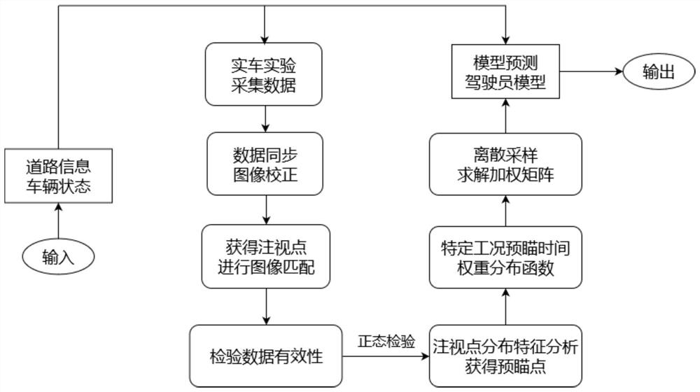
[0052] like figure 1 As shown, the present invention provides a driver's visual fusion method for automatic driving trajectory tracking, including the following implementation process:
[0053] Step 1, experimental design and data collection.
[0054] Experimental equipment: glasses-type eye tracker, to obtain the image information of the driver's gaze point (image coordinate system) and the driver's perspective; a driving recorder, to eliminate image shake; an experimental vehicle with an open CAN bottom layer protocol, which can collect driving information in real time Manipulation behavior information, vehicle kinematics and dynamics information; CAN line signal collector can record CAN signals and collect experimental monitoring data.
[0055] Since the glasses-type eye...
PUM
 Abstract
Description
Claims
Application Information