
Multi-channel high-speed data alignment method and multi-channel high-speed data alignment device

A high-speed data, multi-channel technology, applied in the field of communication, can solve problems such as data transmission delay and jitter, complex circuit design, and impact

Active Publication Date: 2020-10-20
FENGHUO COMM SCI & TECH CO LTD +1
View PDF9 Cites 2 Cited by
  • Summary
  • Abstract
  • Description
  • Claims
  • Application Information

AI Technical Summary

Problems solved by technology

However, the main disadvantage of this method is that the circuit design is complex, and the addition of alignment marks increases the transmission overhead, and has an adverse effect on the delay and jitter of data transmission.

Method used


Image

  • Multi-channel high-speed data alignment method and multi-channel high-speed data alignment device
  • Multi-channel high-speed data alignment method and multi-channel high-speed data alignment device
  • Multi-channel high-speed data alignment method and multi-channel high-speed data alignment device

Examples


Embodiment 1

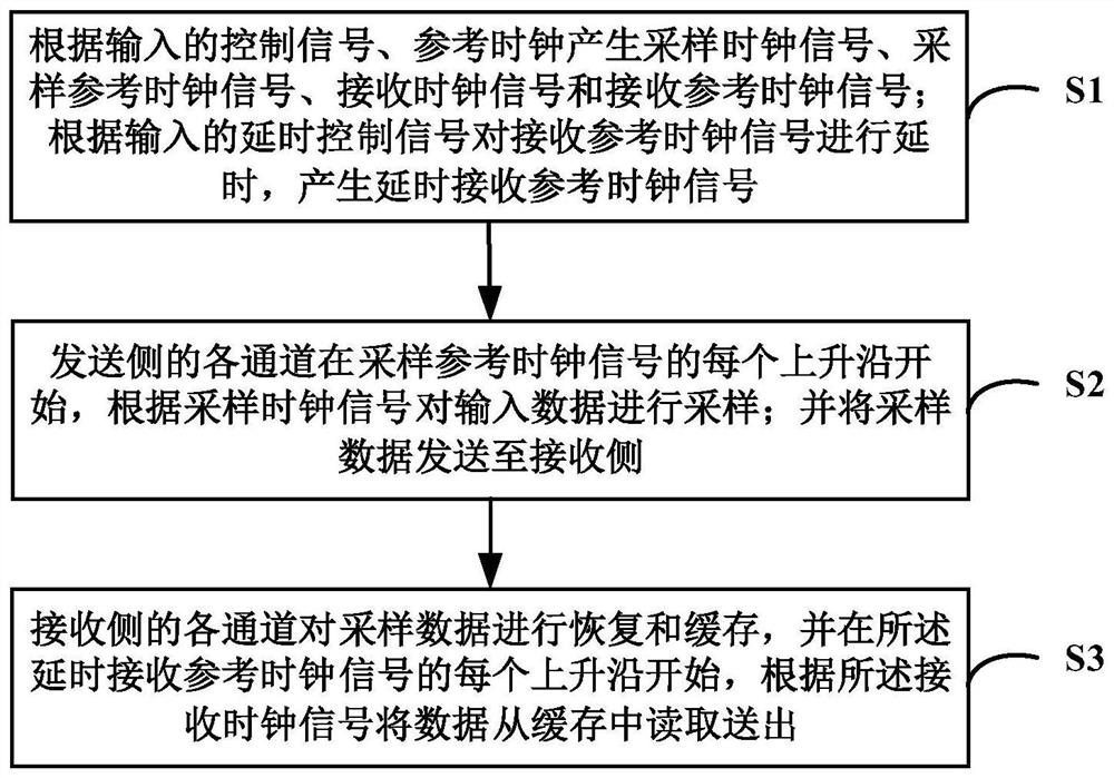
[0048] see figure 1 As shown, this embodiment provides a method for multi-channel high-speed data alignment, the method includes the following steps:

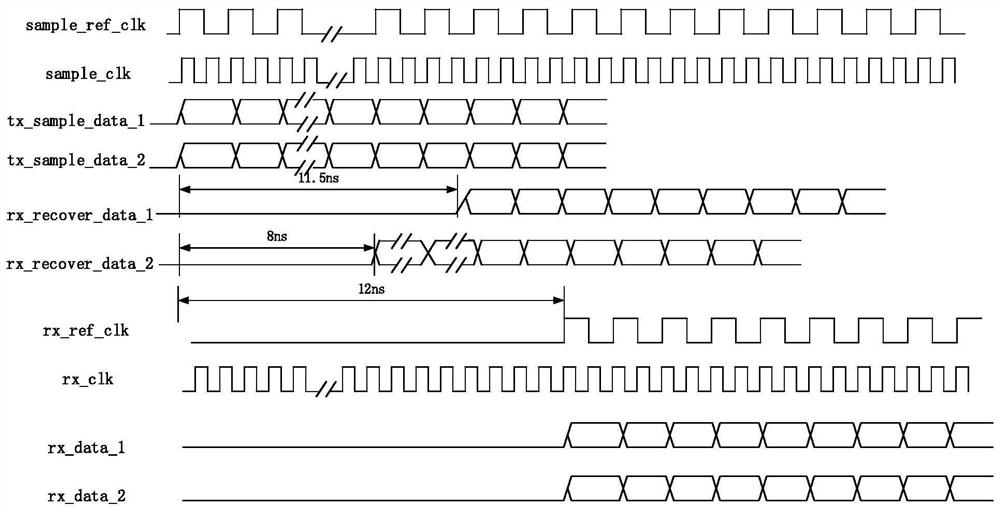
[0049] S1. Generate sampling clock signal (sample_clk), sampling reference clock signal (sample_ref_clk), receiving clock signal (rx_clk) and receiving reference clock signal (rx_ref_clk') according to the input control signal and reference clock (ref_clk); according to the input delay The control signal delays rx_ref_clk' to generate a delayed reception reference clock signal (rx_ref_clk). In practical applications, after the device is started, it will continue to generate the above signals.

[0050] S2. Each channel on the sending side starts at each rising edge of sample_ref_clk, samples input data (such as tx_data_1, tx_data_2, ..., tx_data_n) according to sample_clk; and samples the data (such as tx_sample_data_1, tx_sample_data_2, ..., tx_sample_data_n) ) to the receiving side. In practical applications, each channel h...

Embodiment 2

[0069] see Figure 4 As shown, based on the same inventive concept, an embodiment of the present invention also provides a multi-channel high-speed data alignment device, which includes a control side, a sending side, and a receiving side.

[0070] The control side includes a signal generation module and a signal delay module. Among them, the signal generation module is used to: generate a sampling clock signal (sample_clk), a sampling reference clock signal (sample_ref_clk), a receiving clock signal (rx_clk) and a receiving reference clock signal (rx_ref_clk') according to the input control signal and the reference clock (ref_clk) ). The signal delay module is configured to: delay rx_ref_clk' according to the input delay control signal to generate a delayed reception reference clock signal (rx_ref_clk). In practical applications, after the device is started, it will continue to generate the above signals.

[0071] The sending side includes multiple groups of data sampling ...


PUM


Abstract

The invention discloses a multi-channel high-speed data alignment method and device, and relates to the technical field of communication. The method comprises the following steps: generating a sampling clock signal, a sampling reference clock signal, a receiving clock signal and a receiving reference clock signal according to an input control signal and a reference clock; and delaying the receivedreference clock signal according to the input delay control signal to generate a delayed received reference clock signal, wherein each channel of the sending side starts from each rising edge of thesampling reference clock, and input data is sampled according to the sampling clock signal; recovering and caching the sampled data by each channel on the receiving side, and reading and sending out the data from the cache according to the receiving clock from each rising edge of the delayed receiving reference clock signal. According to the invention, while multi-channel high-speed data alignmentis realized, the introduced delay and jitter are effectively reduced and determined, and the actual application requirements are met.

Description

technical field [0001] The invention relates to the field of communication technology, in particular to a method and device for multi-channel high-speed data alignment. Background technique [0002] In the field of communication, high-speed data transmission is carried out in a serial manner through high-speed driving devices and receiving devices, such as the serial sending and receiving parts of Serdes (Serializer, serializer; Deserializer, deserializer), On the sending side, Serdes performs parallel-to-serial conversion on the received parallel data, and then sends it through the serial sending part; on the receiving side, the receiving part recovers the clock and data according to the received serial data, and then performs serial-to-parallel conversion. [0003] Currently, for transmission rates below 10Gbps (10Gigabits per Second, 10G bits per second), corresponding serial sending and receiving devices can be found for transmission. However, when the transmission rate...

Claims


Application Information

Patent Timeline
IPC IPC(8): H03K3/017H03K17/28
CPCH03K3/017H03K17/28
Inventor 杨彦波郝鹏李恒
Owner FENGHUO COMM SCI & TECH CO LTD
Learn More