
Electric flyswatter

An electric fly, electric technology, applied in the field of intelligent fly removal, can solve the problems of poor fly effect and large energy consumption

Active Publication Date: 2020-10-23
王利娜
View PDF18 Cites 0 Cited by
  • Summary
  • Abstract
  • Description
  • Claims
  • Application Information

AI Technical Summary

Problems solved by technology

[0004] By retrieving the above-mentioned inventions and the fly swatters of the prior art, it is found that people are basically manual, which not only does not have a good effect on swatting flies, but also consumes a lot of physical strength; therefore, we urgently need to invent an electric fly swatter to solve the problem. The above technical issues

Method used


Image

  • Electric flyswatter
  • Electric flyswatter
  • Electric flyswatter

Examples


Embodiment Construction

[0023] The technical solutions of the present invention will be further specifically described below through the embodiments and in conjunction with the accompanying drawings. In the following description, many specific details are set forth in order to fully understand the present invention, but the present invention can be implemented in many other ways different from those described here, and those skilled in the art can do similar Modifications, and therefore the present invention is not limited to the specific examples disclosed below.

[0024] In the description of the present invention, it should be noted that the orientation or positional relationship indicated by the terms "up", "down", "front", "rear", "left", "right" etc. are based on the Orientation or positional relationship, or the orientation or positional relationship that the inventive product is usually placed in use, is only for the convenience of describing the present invention and simplifying the descript...


PUM


Abstract

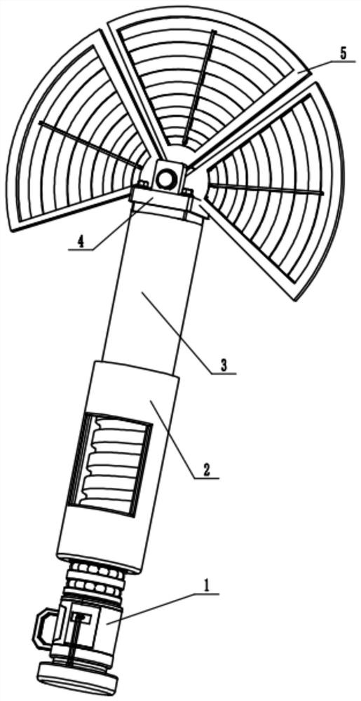
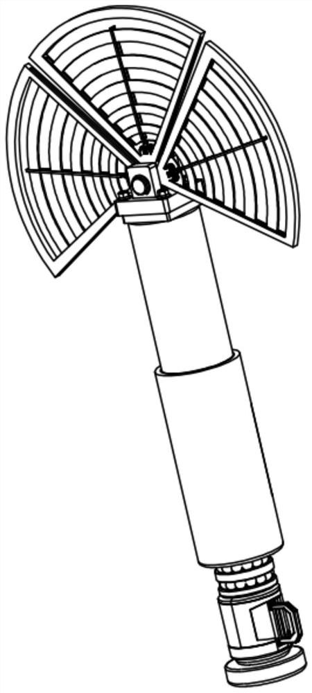
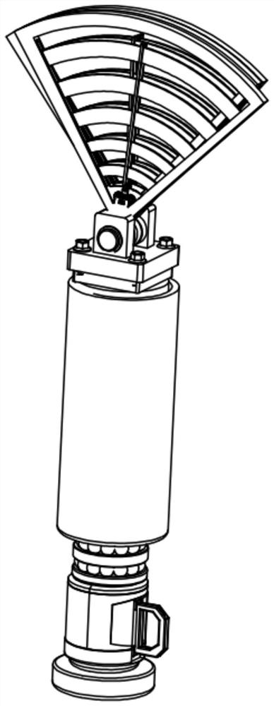
The invention discloses an electric flyswatter. The electric flyswatter comprises a power output mechanism, a bottom moving mechanism, a top moving mechanism, a fixed support mechanism and an electricflyswatter mechanism, wherein the power output mechanism comprises an electric motor, a rolling bearing and a rolling body; the electric motor is fixedly installed on the lower end face of the rolling bearing, a motor shaft of the electric motor is fixedly connected with the rolling body, and the rolling body is arranged in the rolling bearing. Rotation and stretching of the electric flyswatter mechanism are achieved through cooperation of the bottom moving mechanism and the top moving mechanism; the electric motor drives a lead screw, so that the lead screw drives a threaded sleeve to rotate, the threaded sleeve contracts and extends towards the interior of a bottom sleeve, extension of the electric flyswatter mechanism can be achieved, and the electric flyswatter mechanism is more convenient to use; and due to the fact that the threaded sleeve contracts or extends in a rotating mode, rotation of the electric flyswatter mechanism is achieved, and the electric shock range can be effectively enlarged through rotation of the electric flyswatter mechanism.

Description

technical field [0001] The invention relates to the technical field of intelligent fly removal, in particular to an electric fly swatter. Background technique [0002] Flies and some mosquitoes can be seen no matter when and where; especially the existence of flies is the most taboo in the food processing industry and catering industry; flies can mechanically carry and spread various pathogens, and it has been confirmed that the bacteria that flies can carry There are more than 100 kinds, about 30 kinds of protozoa, and 20 kinds of viruses; nowadays, flies usually need to be beaten manually with a slap, which is time-consuming and laborious; [0003] By searching the existing technology, it is found that the fly swatters are basically manual. For example, the Chinese utility model patent No. 201921373755.0 discloses a fly swatter, which includes a handle, anti-slip lines, a ring, and also includes a handle set on the swatter. One side of the handle is used for the racquet h...

Claims


Application Information

Patent Timeline
IPC IPC(8): A01M3/02H02K7/06F16H25/20B08B1/00
CPCA01M3/025A01M3/022H02K7/06F16H25/20B08B1/00Y02A50/30
Inventor 王利娜
Owner 王利娜
Learn More