AI technical title is built by PatSnap AI team. It summarizes the technical point description of the patent document.
A sweeping robot and jet technology, applied in the field of robotics, can solve the problems of inability to sweep and wipe the floor, unable to store matches, cigarette butts, sensor damage, etc.
Inactive Publication Date: 2020-10-23
BEIHUA UNIV
View PDF0 Cites 2 Cited by
Summary
Abstract
Description
Claims
Application Information
AI Technical Summary
This helps you quickly interpret patents by identifying the three key elements:
Problems solved by technology
Method used
Benefits of technology
Problems solved by technology
[0002] In modern life, sweeping robots have already spread to thousands of households, and the safety of sweeping robots is also a top priority. Traditional sweeping robots cannot store matches, cigarette butts and other flammable items due to material and structural reasons, and more sensors are prone to damage. Unable to combine sweeping and mopping, this device solves the above problems
Method used
Image
Click on the blue label to locate the original text in one second.
Reading with bidirectional positioning of images and text.
Examples
specific Embodiment approach 1
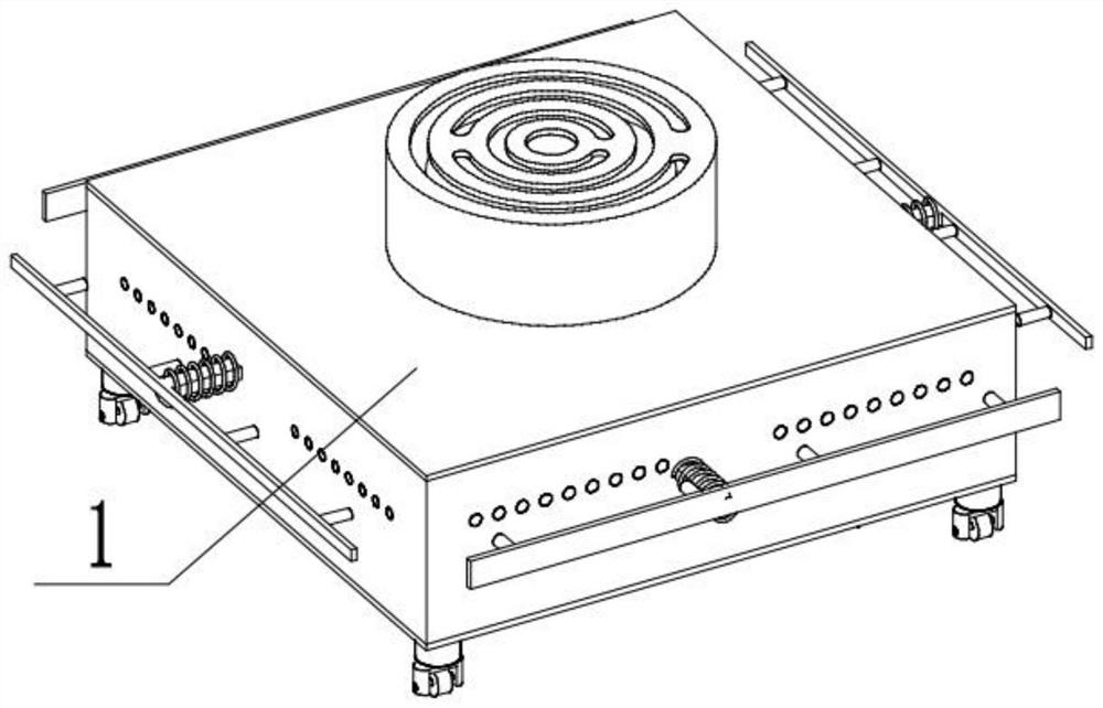
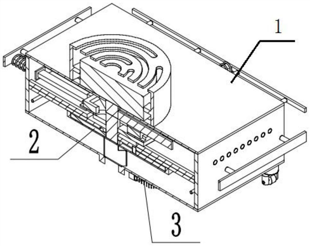
[0035] Combine below Figure 1-20 Describe this embodiment, an automatic sensing jet-type sweeping robot, including a power assembly 1, a dust collection assembly 2, and a mopping assembly 3, and the dust collection assembly 2 and the mopping assembly 3 are all combined with dust collection Body 2 is connected.
specific Embodiment approach 2
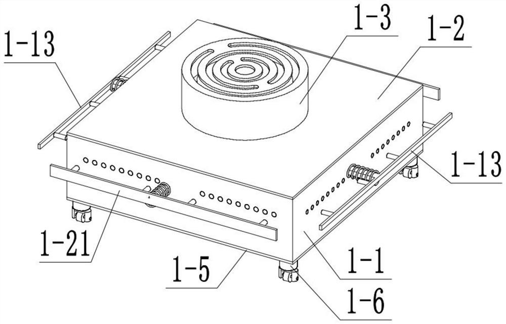
[0037] Combine below Figure 1-20Describe this embodiment, this embodiment will further explain the first embodiment, the power assembly 1 includes a box body 1-1, an upper end cover 1-2, a motor cover 1-3, a motor bracket 1-4, a lower end cover 1- 5. Travel wheel fixing block 1-6, travel wheel bracket 1-7, travel wheel shaft 1-8, travel wheel 1-9, motor 1-10, motor shaft 1-11, fan blade 1-12, induction plate Ⅰ1- 13. Inclined rod Ⅰ1-14, inclined rod limit piece Ⅰ 1-15, spring Ⅰ1-16, reset column Ⅰ1-17, upper slide 1-18, jet control blocking rod Ⅰ1-19, upper slide limit bracket 1- 20. Induction plate Ⅱ1-21, slanting rod Ⅱ1-22, slanting rod limit piece Ⅱ1-23, spring Ⅱ1-24, reset column Ⅱ1-25, sliding plate 1-26, jet control blocking rod Ⅱ1-27, sliding plate The limit bracket 1-28 and the dust suction port 1-29, the box body 1-1 is connected with the upper end cover 1-2, the upper end cover 1-2 is connected with the motor cover 1-3, and the motor cover 1-3 is connected with the ...
specific Embodiment approach 3
[0039] Combine below Figure 1-20 Describe this embodiment, this embodiment will further explain Embodiment 1, the dust suction assembly 2 includes a middle partition 2-1, an air injection port 2-2, a handle I 2-3, a magnetic blocking plate 2-4, a connecting rod 2- 5. Scraper 2-6, vacuum door 2-7, turntable 2-8, suction shell 2-9, blade 2-10, blade shaft 2-11, blade shaft slide rail 2-12 and filter plate 2- 13. The middle partition 2-1 is connected with the box body 1-1, the air outlet 2-2 is located on the middle partition 2-1, the handle Ⅰ 2-3 is connected with the magnetic blocking board 2-4, and the magnetic blocking board 2- 4 Connect with the connecting rod 2-5, the connecting rod 2-5 is connected with the scraper 2-6, the scraper 2-6 is in contact with the lower end cover 1-5, the suction door 2-7 is connected with the lower end cover 1-5 are hinged, the turntable 2-8 is connected to the motor shaft 1-11, the motor shaft 1-11 is rotatably connected to the middle partit...
PUM
Abstract
The invention relates to the field of robots, particularly to an automatic sensing jet-propelled sweeping robot. In modern life, sweeping robots have been popularized in thousands of households, the safety problem of the sweeping robot is also the most important problem, a traditional sweeping robot cannot contain inflammable objects such as matchsticks, cigarette butts and the like due to materials and structures, more sensors are used and are easy to damage, and floor sweeping and mopping combination cannot be achieved. According to the invention, the automatic sensing jet-propelled sweepingrobot solves the problems in the prior art, uses a pure mechanical structure, and is simple in structure and not easy to damage; after inflammables are collected, due to the fact that jet-propelled power is adopted, heat in a box body is taken away through air injection, so that safety accidents cannot happen when the burning point of the sundries cannot be reached; and the robot can automatically change the direction when colliding with an obstacle, the robot can suck the sundries into equipment to be stored, and automatic mopping can be completed by putting down the mopping assembly after floor sweeping is finished.
Description
technical field [0001] The present invention relates to a kind of robot field, more specifically a kind of automatic sensing jet sweeping robot. Background technique [0002] In modern life, sweeping robots have already spread to thousands of households, and the safety of sweeping robots is also a top priority. Traditional sweeping robots cannot store matches, cigarette butts and other flammable items due to material and structural reasons, and more sensors are prone to damage. Unable to combine sweeping and mopping, this device solves the above problems. Contents of the invention [0003] The purpose of the present invention is to provide an automatic sensing jet sweeping robot, which can automatically change direction when encountering an obstacle, can suck up debris and dust on the ground, and can wipe the ground. [0004] The purpose of the present invention is achieved through the following technical solutions: [0005] An automatic sensing jet sweeping robot, inclu...
Claims
Application Information
Patent Timeline
Application Date:The date an application was filed.
Publication Date:The date a patent or application was officially published.
First Publication Date:The earliest publication date of a patent with the same application number.
Issue Date:Publication date of the patent grant document.
PCT Entry Date:The Entry date of PCT National Phase.
Estimated Expiry Date:The statutory expiry date of a patent right according to the Patent Law, and it is the longest term of protection that the patent right can achieve without the termination of the patent right due to other reasons(Term extension factor has been taken into account ).
Invalid Date:Actual expiry date is based on effective date or publication date of legal transaction data of invalid patent.

