
Chamfering clamp for shaft part tooth profile

A technology for shaft parts and tooth profiles, applied in the field of chamfering fixtures for shaft parts, can solve the problems of limited axial space and inability to add clamping mechanisms

Pending Publication Date: 2020-10-23
BAOJI FAST GEAR
View PDF0 Cites 0 Cited by
  • Summary
  • Abstract
  • Description
  • Claims
  • Application Information

AI Technical Summary

Problems solved by technology

Since the shaft parts are generally long and the axial space is limited, it is impossible to add a clamping mechanism (hydraulic or pneumatic) chamfering fixture in the axial direction

Method used


Image

  • Chamfering clamp for shaft part tooth profile
  • Chamfering clamp for shaft part tooth profile
  • Chamfering clamp for shaft part tooth profile

Examples


Embodiment Construction

[0027] Specific embodiments of the present disclosure will be described in detail below in conjunction with the accompanying drawings. It should be understood that the specific embodiments described here are only used to illustrate and explain the present disclosure, and are not intended to limit the present disclosure.

[0028] In the present disclosure, unless stated otherwise, the orientation words used such as "upper, lower", "horizontal, vertical", "top, bottom" are usually defined based on the drawings of the corresponding drawings, "Inside and outside" refer to the inside and outside of the outline of the corresponding component, and usually refer to the definition based on the drawings of the corresponding drawings.

[0029] The present invention is described in further detail below in conjunction with accompanying drawing:

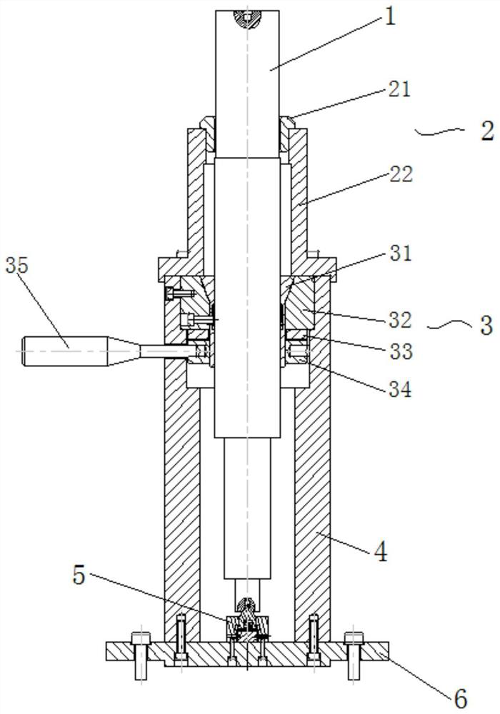
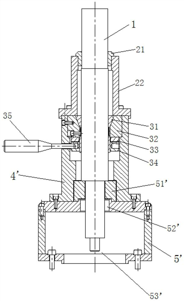
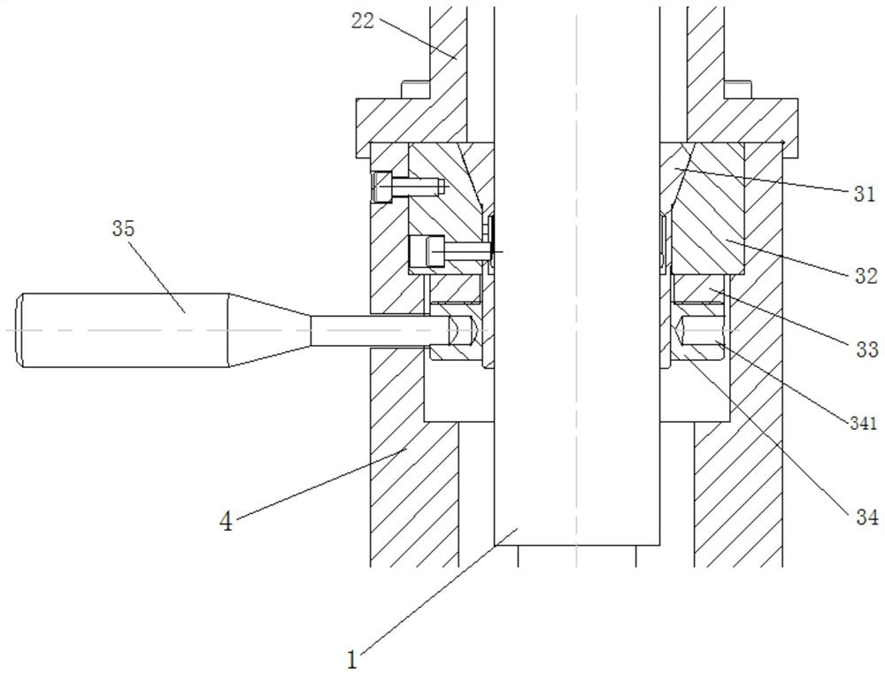
[0030] combine Figure 1-7 , the present invention provides a tooth profile chamfering fixture for shaft parts. A cylindrical support body 4 or...


PUM


Abstract

The invention discloses a chamfering clamp for a shaft part tooth profile. A cylindrical supporting body is arranged, a clamping assembly is coaxially arranged in the supporting body, and the clampingassembly comprises a tensioning body and a radial limiting body which are sequentially arranged in a sleeved mode from inside to outside; and an adjusting body further sleeves the tensioning body, radial displacement of the adjusting body is converted into axial displacement, the adjusting body drives the tensioning body and the radial limiting body to move relatively in the axial direction, andthe tensioning body is forced to be tightened in the radial direction. According to the chamfering clamp, through reasonable arrangement of a clamp structure, when the clamp is used for machining shaft parts, no axial power mechanism needs to be additionally arranged, and the purpose of axially clamping the part is achieved.

Description

technical field [0001] The invention belongs to the field of processing tooling, in particular to a jig for chamfering tooth profiles of shaft parts. Background technique [0002] At present, domestic gear tooth profile chamfering is mainly done by hand or edge grinding, and the main realization is disc gears. Since the shaft parts are generally long and the axial space is limited, it is impossible to add a clamping mechanism (hydraulic or pneumatic) chamfering fixture in the axial direction. Contents of the invention [0003] To solve this technical problem, the present invention provides a tooth profile chamfering jig for shaft parts, which can achieve the goal of axial clamping jig without adding an axial power mechanism. [0004] In order to solve the problems referred to above, the technical scheme that the present invention takes comprises: [0005] A tooth profile chamfering fixture for shaft parts, a cylindrical support body is provided, and a clamping assembly i...

Claims


Application Information

Patent Timeline
IPC IPC(8): B23F23/06B23F19/12B23F19/10
CPCB23F19/10B23F19/12B23F23/06
Inventor 乔茂
Owner BAOJI FAST GEAR
Learn More