
Gravity-removing positioning clamp for to-be-edge-sealed contactor with L-shaped mounting frame

A contactor and mounting frame technology, applied in the field of edge banding fixtures, can solve problems such as large deviation, unqualified device sealing, and inability to meet the precise positioning of the contactor.

Active Publication Date: 2020-10-23
贵州振华群英电器有限公司(国营第八九一厂)
View PDF6 Cites 0 Cited by
  • Summary
  • Abstract
  • Description
  • Claims
  • Application Information

AI Technical Summary

Problems solved by technology

If we follow the traditional positioning method relying on gravity, the deformation size and direction of each device's mounting frame will be infinitely magnified under a 170 times microscope during laser edge sealing, resulting in a deviation of the coordinates of each device relative to the zero point of the housing after positioning More than 0.3mm, and the positioning accuracy of laser edge sealing requires a deviation of no more than 0.02mm, otherwise the device’s sealing performance will be unqualified due to the deviation of the laser track, and the traditional gravity positioning method can no longer meet the precise positioning of the contactor in laser welding technology
[0004] The current gravity positioning method is to support the bottom surface of the edge-sealing contactor of the L-shaped mounting frame with a fixture. Due to the influence of the resistance welding deformation of the L-shaped mounting frame, the deviation after positioning and locking is relatively large

Method used


Image

  • Gravity-removing positioning clamp for to-be-edge-sealed contactor with L-shaped mounting frame
  • Gravity-removing positioning clamp for to-be-edge-sealed contactor with L-shaped mounting frame
  • Gravity-removing positioning clamp for to-be-edge-sealed contactor with L-shaped mounting frame

Examples


Embodiment Construction

[0024] The technical solution provided by the present invention will be further described in detail in conjunction with the accompanying drawings and specific embodiments.

[0025] In order to solve the problem that the existing gravity positioning method has low positioning accuracy and cannot meet the precise positioning of the contactor in the laser welding technology, the present invention provides a gravity-free positioning method for the contactor with an L-shaped mounting frame. The bottom surface of the contactor to be sealed with the L-shaped mounting bracket is suspended in the air when it is positioned.

[0026] This positioning method can be realized by any positioning fixture. The specific steps are to first position the edge contactor with the L-shaped mounting frame in the fixture, and then lift the edge-sealing contactor with the L-shaped mounting frame. The bottom surface is suspended in the air to complete the positioning, and then the edge sealing is welded ...


PUM


Abstract

The invention provides a gravity-removing positioning method and a positioning clamp for a contactor with an L-shaped mounting frame. According to the method, the bottom surface of the to-be-edge-sealed contactor with the L-shaped mounting frame is suspended when the to-be-edge-sealed contactor is positioned, and the welding surface formed after a housing is matched with a base is directly positioned, so that the precision of the laser focal length in the welding process is improved. The influence of welding deformation of the mounting frame and the contactor housing on the positioning precision is eliminated, and precise positioning is ensured. The deviation range of the positioning precision is 0.01-0.04 mm, and the positioning precision is improved by more than 10 times.

Description

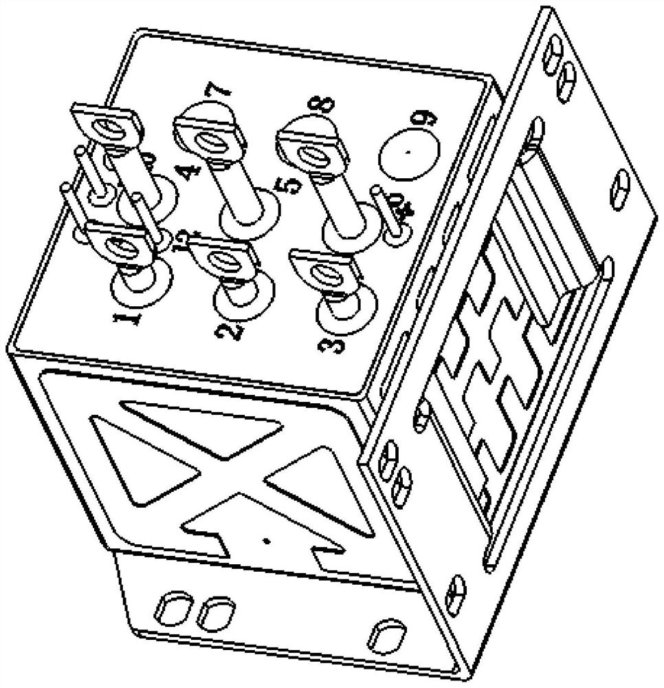
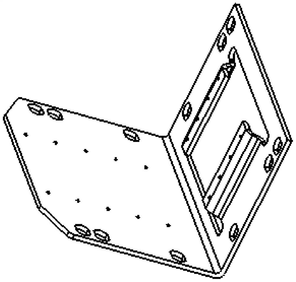
technical field [0001] The invention relates to an edge-sealing fixture, in particular to a degravity positioning method and a positioning fixture for a contactor with an L-shaped mounting frame. Background technique [0002] With the rapid development of my country's military technology, the overall sealing quality level of military sealed electronic components is getting higher and higher. Since the positioning accuracy of sealing components directly determines the accuracy of laser operation, the precise positioning of laser sealing components put forward higher requirements. Especially some sealing devices with special installation methods, such as contactors with L-shaped mounting brackets, such as figure 1 As shown, the structure of the L-shaped mounting bracket is as follows figure 2 shown. [0003] At present, the installation method of the contactor mounting frame is mainly realized by laser welding technology. The specific method is to first combine the mounting...

Claims


Application Information

Patent Timeline
IPC IPC(8): B23K26/21B23K26/70
CPCB23K26/21B23K26/702
Inventor 饶永马兴吴建荣曾乾嵘
Owner 贵州振华群英电器有限公司(国营第八九一厂)
Learn More