Limiting block sealing device and vacuumizing tire mold

A technology of sealing device and limit block, which is applied in the field of tire production, can solve the problems of poor sealing effect of equipment and failure to achieve sealing effect, etc.

Pending Publication Date: 2020-10-23
合肥大道模具有限责任公司
View PDF0 Cites 0 Cited by
  • Summary
  • Abstract
  • Description
  • Claims
  • Application Information

AI Technical Summary

Problems solved by technology

[0003] When the traditional vacuum mold solves the sealing effect of the bolt hole joint, copper sheets and other methods are routinely used, and the steel parts are in contact with the steel parts, which cannot achieve the sealing effect, resulting in poor sealing effect of the equipment

Method used


Image

  • Limiting block sealing device and vacuumizing tire mold
  • Limiting block sealing device and vacuumizing tire mold
  • Limiting block sealing device and vacuumizing tire mold

Examples


Embodiment Construction

[0025] The present invention will be further described below in conjunction with the accompanying drawings and embodiments.

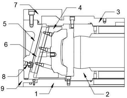
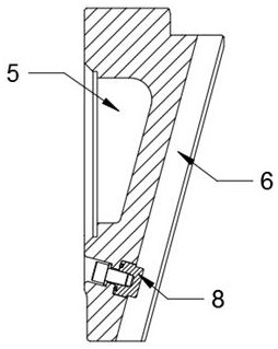
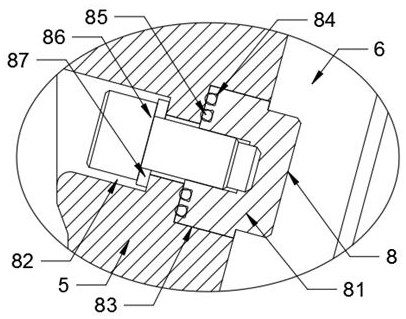
[0026] Please refer to figure 1 , figure 2 , image 3 , Figure 4 , Figure 5 and Figure 6 ,in, figure 1 A schematic diagram of the overall structure provided for the present invention; figure 2 Schematic diagram of the bonding structure of the guide ring and the inner template provided by the present invention; image 3 Schematic diagram of the seal structure provided by the present invention; Figure 4 A schematic diagram of the sealing structure at the bottom of the guide ring provided by the present invention; Figure 5 Schematic diagram of the pattern mold structure provided by the present invention; Figure 6 It is a schematic diagram of the fastening structure of the upper cover provided by the present invention. The limiting block sealing device and the vacuumized tire mold include: a bottom plate 1, a sidewall plate 2 and an upper ...


PUM


Abstract

The invention provides a limiting block sealing device and a vacuumizing tire mold. The limiting block sealing device comprises a bottom plate, a tire side plate and an upper cover, wherein the uppercover is arranged above the bottom plate in parallel; the tire side plate is fixedly between the bottom plate and the upper cover in a sealing and fitting mode; a pattern mold is correspondingly arranged on one side of the tire side plate, and the pattern mold is fixedly connected with the bottom plate and the upper cover; and an inner mold plate is mounted on the outer wall of the pattern mold ina fitting mode. The limiting block sealing device of the vacuumizing tire mold is extruded and limited through a double-layer installed sealing ring, and the sealing ring is used as a transition, sothat the sealing between steel parts is achieved, the air flow of an outer cavity of the mold and an inner cavity of the mold is effectively blocked, the good sealing effect of the bolt hole connection part of the vacuumizing mold is achieved, and the vacuum degree requirement of the inner cavity of the mold is ensured; and the structure adopts a static sealing mode, so that the sealing effect ofthe bolt hole part is achieved, and the phenomenon that the sealing ring can fail due to deformation after long-term use is avoided.

Description

technical field [0001] The invention relates to the technical field of tire production, in particular to a limiting block sealing device and a vacuumized tire mold. Background technique [0002] With the continuous update of the tire market demand, now most of the large-size AT and MT tires have patterns on the sidewall, which requires the tire mold to use a positioning structure when designing, which can realize the pattern docking, vacuumize the mould, and vulcanize. When it comes to tires, the sidewall and pattern blocks will directly determine the appearance of the tire. The sidewall is a ring, and the pattern blocks are distributed around the circumference of the sidewall. [0003] When the traditional vacuum mold solves the sealing effect of the bolt hole joint, copper sheets and other methods are routinely used, and the steel parts are in contact with the steel parts, which cannot achieve the sealing effect, resulting in poor sealing effect of the equipment. [0004]...

Claims


Application Information

Patent Timeline
Patent Type & Authority Applications(China)
IPC IPC(8): B29C33/00B29C33/42B29C33/30B29L30/00
CPCB29C33/0038B29C33/301B29C33/424B29L2030/003
Inventor 左武宋家文姚道发
Owner 合肥大道模具有限责任公司
Why Eureka
Try Eureka