Quick mould changing mechanism used for injection molding processing

A technology of injection molding processing and injection molding machines, which is applied in the field of quick mold change mechanism for injection molding processing, and can solve problems such as wasting workers' working time, installation deviation, front and back mold assembly, etc.

Active Publication Date: 2020-10-23
长春百思特汽车零部件有限公司
View PDF13 Cites 4 Cited by
  • Summary
  • Abstract
  • Description
  • Claims
  • Application Information

AI Technical Summary

Problems solved by technology

[0005] 1. Although this solution can quickly clamp the mold and realize quick mold change, this equipment needs to clamp and disassemble the front and back molds twice, and when installing the mold, it also needs to carry out two times of front and back molds Clamping installation, mold change process is too slow
[0006] 2. The installation accuracy of the mold is too high, and the installation deviation of the front and back molds often occurs when the mold is installed separately.
[0007] 3. When the mold is clamped and replaced, the positive and negative molds are often clamped to two places, and the positive and negative molds cannot be assembled together. Workers are required to assemble them together, which wastes a lot of working time for workers.
[0008] 4. When the mold is installed, the mold of this scheme is in a cold state. After the mold is installed, it is necessary to heat the front and back molds, which wastes a lot of working time for workers

Method used


Image

  • Quick mould changing mechanism used for injection molding processing
  • Quick mould changing mechanism used for injection molding processing
  • Quick mould changing mechanism used for injection molding processing

Examples


Embodiment Construction

[0054] The technical solutions of the present invention will be further described below in conjunction with the accompanying drawings and through specific implementation methods.

[0055] Wherein, the accompanying drawings are only for illustrative purposes, showing only schematic diagrams, rather than physical drawings, and should not be construed as limitations on this patent; in order to better illustrate the embodiments of the present invention, some parts of the accompanying drawings will be omitted, Enlarged or reduced, does not represent actual product size.

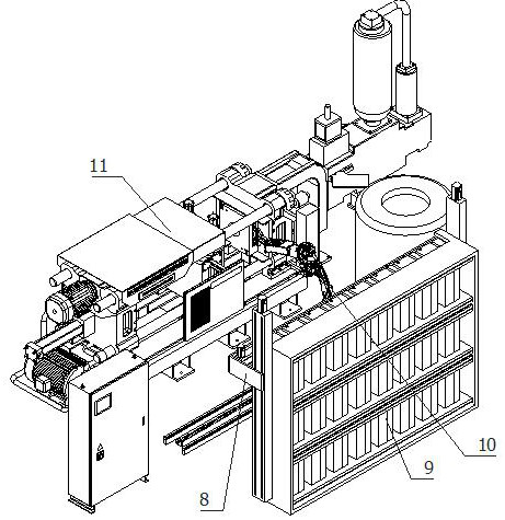
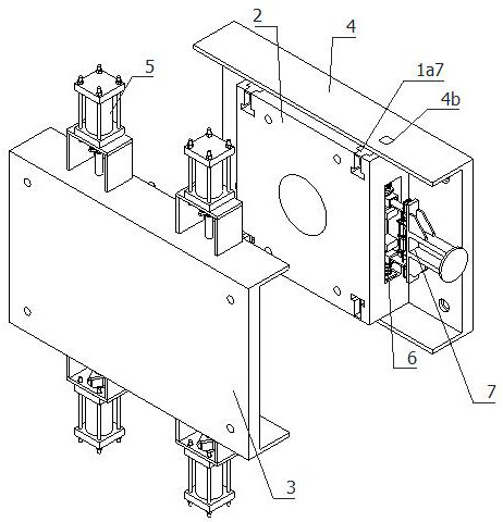
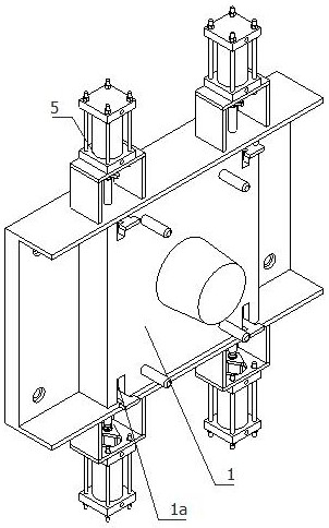
[0056] refer to Figure 1 to Figure 16 A quick mold change mechanism for injection molding shown includes an injection molding machine 11, a positive mold base 3 and a negative mold base 4 installed on the injection molding machine 11, and also includes a positive mold 1, a negative mold 2, and a jaw moving mechanism 10 , an elastic inserting mechanism 6, a mechanical gripper 7, a preheating mechanism 8, a placem...


PUM


Abstract

The invention relates to the field of injection molding processing, in particular to a quick mould changing mechanism used for injection molding processing. The quick mould changing mechanism comprises an injection molding machine, a positive mould seat and a negative mould seat, wherein the positive mould seat and the negative mould seat are installed on the injection molding machine. The quick mould changing mechanism also comprises a positive mould, a negative mould, a clamping claw movement mechanism, an elastic tight-plugging mechanism, a mechanical clamping claw, a preheating mechanism,a placement frame and four demoulding mechanisms. The quick mould changing mechanism used for injection molding processing preheats a mould on the placement frame through a preheating mechanism so asto prevent a worker from transporting the mould, a possibility that the worker is at risk is lowered, a situation that the positive mould and the negative mould are clamped and installed for two timescan be avoided, and a mould replacement process is quickened. Since the positive mould is taken down from the negative mould, a possibility that mould installation has a deviation is lowered, the positive mould and the negative mould are tightly connected, only one-time clamping and disassembling needs to be carried out, a mould replacement process is quickened, a situation that the positive mould and the negative module are assembled by the worker is not required, the positive mould and the negative mould are assembled into a whole, and land occupation of the mould is reduced.

Description

technical field [0001] The invention relates to the field of injection molding processing, in particular to a quick mold change mechanism for injection molding processing. Background technique [0002] Injection molding machine is also known as injection molding machine or injection machine. It is the main molding equipment for making thermoplastics or thermosetting plastics into various shapes of plastic products with plastic molding molds. When replacing the mold on the injection molding machine, the mold is first lifted out of the injection molding machine by a crane, and then passed The crane lifts the new mold into the injection molding machine, and then completes the replacement of the mold. When installing the mold for a small injection molding machine, the worker often moves the mold into the injection molding machine, and then replaces the mold on the injection molding machine. And the handling process is too dangerous. [0003] my country's patent application num...

Claims


Application Information

Patent Timeline
Patent Type & Authority Applications(China)
IPC IPC(8): B29C45/17B29C45/73
CPCB29C45/1756B29C45/1742B29C45/73
Inventor 孙超月洪思宜
Owner 长春百思特汽车零部件有限公司
Why Eureka
Try Eureka