Gas tank unloading device

A technology of unloading device and gas tank, which is applied in the directions of transportation and packaging, loading/unloading, etc., can solve the problems of high risk factor and difficult control, etc.

Active Publication Date: 2020-10-23
徐州多元机械科技有限公司
View PDF8 Cites 1 Cited by
  • Summary
  • Abstract
  • Description
  • Claims
  • Application Information

AI Technical Summary

Problems solved by technology

[0004] Based on the existing gas tank unloading process, the gas tank relies on gravity to accelerate and fall to the ground ...

Method used


Image

  • Gas tank unloading device
  • Gas tank unloading device
  • Gas tank unloading device

Examples


Embodiment 1

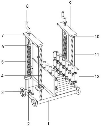
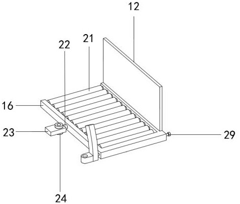
[0030] refer to Figure 1-5 , a gas tank unloading device, comprising a base plate 1 and a top plate 9, the top outer wall of the base plate 1 and the bottom outer wall of the top plate 9 are fixedly connected with a slide bar 5 and a first threaded rod 4 by bolts, and the outer wall of the first threaded rod 4 is threaded. Cover block 24, the outer wall of cover block 24 is connected with base block 23 through bearing, one side outer wall of base block 23 is welded with connecting shaft 22, one end of connecting shaft 22 is connected with unloading plate 16 through bearing, the inner wall of unloading plate 16 A groove is opened, the inner wall of the groove is connected with a roller shaft 21 through a bearing, the top outer wall of the unloading plate 16 is fixed with a side plate 12 by bolts, one side outer wall of the side plate 12 is provided with a guide mechanism, and the outer wall of the slide bar 5 is sleeved with a Slider 15, one side of the outer wall of the slide...

Embodiment 2

[0039] refer to Image 6 , The gas tank unloading device, compared with Embodiment 1, this embodiment also includes a magnetic ball 18 bonded to the top of the strut 17 .

[0040] In the present invention, the top outer wall side of the discharge plate 16 is fixed with a magnetic block 19 by screws, and the magnetic block 19 and the magnetic ball 18 are arranged as opposite magnets.

[0041] During use, after completing the unloading of a gas tank, the release elastic potential energy of the contraction spring 6 will pull the unloading plate 16 upwards under the action of the steel wire 11, the top pulley 10 and the bottom pulley 2. At this time, the magnetic ball 18 and the magnetic block 19 under the action of the opposite magnetic force, first slide the slider 29 to the bottom inner wall of the slide rail 29 again, and the center of gravity of the unloading plate 16 is located at the connection between the steel wire 11 and the base block 23, so that the unloading The slid...


PUM


Abstract

The invention discloses a gas tank unloading device. The following scheme is provided currently in order to solve the problems that when unloaded, gas tanks are manually carried, the carrying workloadis high, the gas tanks speed up to fall to the ground in the falling process under the gravity effect, the gas tanks easily collide with the ground, the gas tanks are not easily controlled, and the danger coefficient is high in the unloading process. The gas tank unloading device comprises a bottom plate and a top plate. The outer wall of the top of the bottom plate and the outer wall of the bottom of the top plate are fixedly connected with a sliding rod and a first threaded rod through bolts, the outer wall of the first threaded rod is connected with a sleeve block through a thread, the outer wall of the sleeve block is connected with a base block through a bearing, a connecting shaft is welded to the outer wall of one side of the base block, one end of the connecting shaft is connectedwith an unloading plate through a bearing, and a groove is formed in the inner wall of the unloading plate. The gravitational potential energy of the gas tanks is converted into the elastic potentialenergy of shrinking springs, unloading of the gas tanks slows down, the gas tank unloading device is safe and reliable and easy to control, the manpower is saved, and potential safety hazards of collisions during manual carrying to the gas tanks are eliminated.

Description

technical field [0001] The invention relates to the technical field of unloading dangerous goods, in particular to a gas tank unloading device. Background technique [0002] Rural life in our country has basically bid farewell to the living habits of firewood and fire, and turned to coal gas, which is liquefied petroleum gas. The population base in rural areas in my country is large and the proportion is high. Every year, a family needs to replace new liquefied gas tanks many times, so for liquefied petroleum gas For the staff, a large number of gas tanks are unloaded every day, which is a heavy and dangerous job. [0003] Since the gas tank weighs about 60 catties when it is full, the current gas tank is unloaded by manpower, and the load of the work is heavy. The risk factor in the fueling process is high, and the existing patents are not easy to solve this type of problem. Therefore, a gas tank unloading device is urgently needed to solve the above problems. Contents of ...

Claims


Application Information

Patent Timeline
IPC IPC(8): B65G67/30
CPCB65G67/30
Inventor 江小燕
Owner 徐州多元机械科技有限公司
Why Eureka
Try Eureka