
Automobile oil pipe connecting device

A connecting device and oil pipe joint technology, which is applied in the direction of threaded connection, pipe/pipe joint/pipe fitting, siphon pipe, etc., can solve problems such as engine failure, serious traffic accidents, and lack of power

Active Publication Date: 2020-10-23
SHANDONG LONGKOU TUBING
View PDF8 Cites 1 Cited by
  • Summary
  • Abstract
  • Description
  • Claims
  • Application Information

AI Technical Summary

Problems solved by technology

[0002] In the existing life, the oil pipe is a metal pipe used to transport fuel oil. It is a very important connecting pipe for providing energy for automobiles. It is widely used in many fields such as automobiles. Now the oil pipe connection method used in automobiles It is relatively unstable, and it will often cause oil leakage or occasionally fall. If the vehicle leaks or falls off during driving, the car will lose control of the vehicle, the engine will not work, the power will be insufficient, and the vehicle will catch fire. In other cases, serious traffic accidents will occur, which is very dangerous.
[0003] Patent No. 201921981468.8 discloses a connecting device for oil pipes of automobile engines. In order to avoid oil leakage from the oil pipes during oil delivery, the hydraulic pressure in the oil pipes will also be different due to different powers. When the hydraulic pressure is too large, due to the sealing Low strength may cause oil to seep from the side wall between the connecting pipe and the fixed pipe. When the sealing ring ages, the sealing effect will be reduced

Method used


Image

  • Automobile oil pipe connecting device
  • Automobile oil pipe connecting device
  • Automobile oil pipe connecting device

Examples


Embodiment Construction

[0028] The present invention will be described in detail below, and the technical solutions in the embodiments of the present invention will be clearly and completely described. Apparently, the described embodiments are only some of the embodiments of the present invention, not all of them. Based on the embodiments of the present invention, all other embodiments obtained by persons of ordinary skill in the art without making creative efforts belong to the protection scope of the present invention.

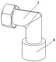
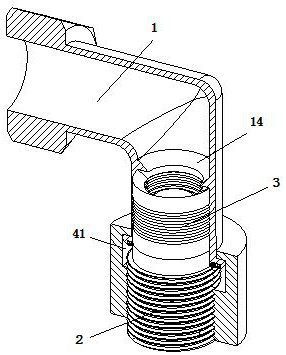
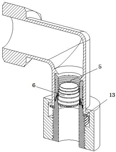
[0029] The present invention provides a kind of automobile oil pipe connection device here through improvement, as Figure 1-Figure 9 As shown, it includes a fuel pipe joint 1 installed at the end of the oil pipe, an oil pipe joint 2 welded on the oil port of the cylinder block, and a turbulence mechanism 3 arranged in the oil pipe joint 1, and the oil pipe joint 1 passes through the threaded sleeve 4 is fixedly connected with the outer side of the oil joint 2, and the spoiler mech...


PUM


Abstract

The invention relates to the technical field of automobile manufacturing, in particular to an automobile oil pipe connecting device. The automobile oil pipe connecting device comprises an oil pipe joint mounted at the end of an oil pipe, an oil path joint welded to an oil path port of a cylinder body, and a disturbed flow mechanism arranged in the oil pipe joint, wherein the oil pipe joint is fixedly connected with the outer side of the oil path joint through a screwed sleeve; the disturbed flow mechanism comprises a sealed rubber pipe fitting and a disturbed flow barrel fitting; a step-shapedclamping connection barrel is integrally shaped and arranged at the port of the oil path joint; and the sealed rubber pipe fitting comprises a disturbed flow intercepting segment and a pressure sealintercepting segment, a plurality of annular inner inversed tooth grooves are formed in the disturbed flow intercepting segment, a step-shaped pressure oil passing cavity is formed in the pressure seal intercepting segment, and a plurality of clamping connection joints are arranged outside the disturbed flow barrel fitting. The automobile oil pipe connecting device disclosed by the invention can realize multiple sealing effects; and through a disturbed flow mechanism, the sealed rubber pipe fitting is stressed to expand outwards but is always closely attached to the inner side of the oil pipejoint, so that sealing intensity is greatly improved.

Description

technical field [0001] The invention relates to the technical field of automobile manufacturing, in particular to an automobile oil pipe connecting device. Background technique [0002] In the existing life, the oil pipe is a metal pipe used to transport fuel oil. It is a very important connecting pipe for providing energy for automobiles. It is widely used in many fields such as automobiles. Now the oil pipe connection method used in automobiles It is relatively unstable, and it will often cause oil leakage or occasionally fall. If the vehicle leaks or falls off during driving, the car will lose control of the vehicle, the engine will not work, the power will be insufficient, and the vehicle will catch fire. In other cases, more serious traffic accidents will occur, which is very dangerous. [0003] Patent No. 201921981468.8 discloses a connecting device for oil pipes of automobile engines. In order to avoid oil leakage from the oil pipes during oil delivery, the hydraulic...

Claims


Application Information

Patent Timeline
IPC IPC(8): F16L43/00F16L15/04F16L55/04
CPCF16L15/04F16L43/00F16L55/04
Inventor 孙业晓刘照彬孙学源马鹏飞马德婷李殿双孙超王举王丹刘妮隋玉婵石晓娜史世凯
Owner SHANDONG LONGKOU TUBING
Learn More