Lamp post system based on groove mounting structure

A technology for installing structures and lamp poles, which is applied to the parts of lighting devices, lighting devices, lighting auxiliary devices, etc., and can solve the problems of easy rust, reduced strength, and ugly appearance of lamp poles.

Pending Publication Date: 2020-10-23
HUNAN GOLDWELL NEW MATERIALS TECH CO LTD +1
View PDF0 Cites 0 Cited by
  • Summary
  • Abstract
  • Description
  • Claims
  • Application Information

AI Technical Summary

Problems solved by technology

[0003] At present, the functional parts are mainly installed on the light pole by means of hoops or direct screw fastening. Among them, the hoop installation method has the disadvantages of ugly appearance, high cost, and inconvenient installation, and because the hoop itself is easy to loosen and rotation, the fasteners connecting the hoop are also prone to rust and failure due to most of them being exposed, with poor stability and low reliability
The screw fasten

Method used


Image

  • Lamp post system based on groove mounting structure
  • Lamp post system based on groove mounting structure
  • Lamp post system based on groove mounting structure

Examples


Embodiment 1

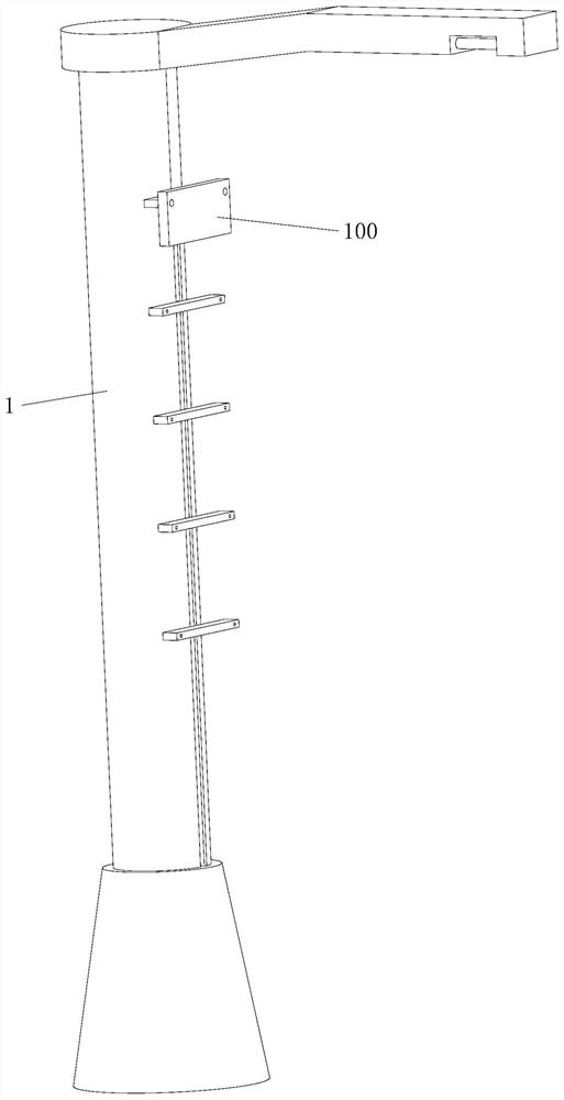
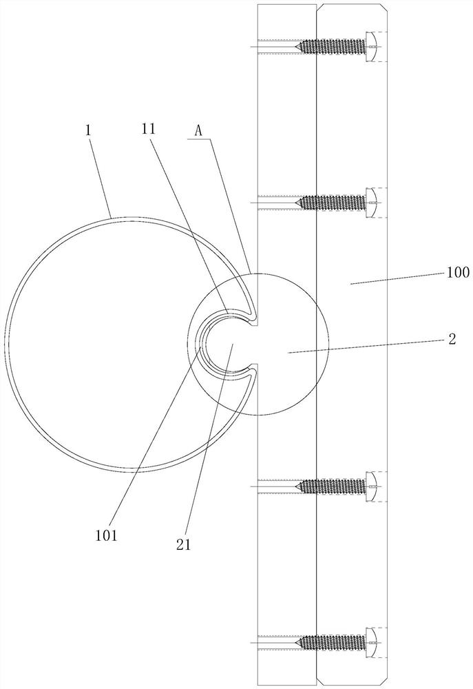
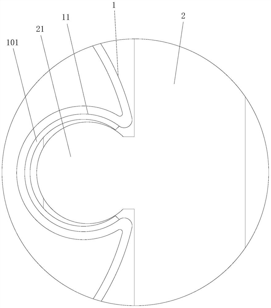
[0034] Such as Figure 1 to Figure 3 As shown, the light pole system based on the groove installation structure of this embodiment includes a light pole main body 1, a plurality of installation bases 2 and a functional part 100. The light pole main body 1 has a installation groove extending along the length direction, The mounting base 2 has a connecting portion 21 placed in the mounting groove, the mounting base 2 is connected with a positioning mechanism for fixing the connecting portion 21 in the mounting groove, and one of the mounting bases 2 is installed with a functional part 100 . The light pole system adopts the light pole main body 1 with a mounting groove, and the connecting part 21 of the mounting base 2 is placed in the mounting groove and fixed by a positioning mechanism. Compared with the traditional installation method, the connecting part 21 is hidden in the mounting groove In addition, the aesthetics can be improved, and the matching structure of the connect...

Embodiment 2

[0041] The light pole system based on the groove installation structure of this embodiment is basically the same as that of Embodiment 1, the main difference is that, as Figure 4 and Figure 5As shown, in the present embodiment, the cross-sections of the bottom groove bottom and the top groove body of the inner expansion groove 11 are rectangular, and the connecting portion 21 can be inserted into the inner expansion groove 11 from the inner expansion groove 11 notch and can be inserted into the inner expansion groove 11. The expansion member positioned between the inner walls on both sides of the inner expansion groove 11 is tightened by rotation. The tensioning member of this embodiment can be a strip, and it is preferable to arrange a tensioning curved surface at both ends of the strip to realize gradual expansion. Specifically, the tensioning member can be a boat nut in the prior art.

[0042] In this embodiment, the connecting part 21 can be inserted into the inner expa...

Embodiment 3

[0044] The light pole system based on the groove installation structure of this embodiment is basically the same as that of Embodiment 1, the main difference is that, as Figure 6 and Figure 7 As shown, in this embodiment, the inner expansion groove 11 is a dovetail groove as a whole, and the positioning mechanism includes a tightening member 102, which is threadedly connected to the mounting base 2, and the tightening member 102 can be screwed to make the The tightening member 102 tightens the inner wall of the inner expansion groove 11 to force the connecting portion 21 to be in close contact with the inner wall of the inner expansion groove 11, or the tightening member 102 is separated from the inner wall of the inner expansion groove 11 so that the connecting portion 21 can move along the inner wall of the inner expansion groove 11. The inner expansion groove 11 moves. When the tightening member 102 tightens the inner wall of the inner expansion groove 11, the tightening...


PUM


Abstract

The invention discloses a lamp post system based on a groove mounting structure. The system involves a lamp post main body, more than one mounting base and more than one functional part, wherein the lamp post main body is provided with a mounting groove extending in the length direction, the mounting base is provided with a connecting part arranged in the mounting groove, the mounting base is connected with a positioning mechanism used for fixing the connecting part in the mounting groove, and at least one functional part is arranged on at least one mounting base. The system has the advantagesof being simple and compact in structure, low in cost, easy and convenient to assemble, high in mounting flexibility, convenient to adjust, good in aesthetic property, good in connection stability and reliability and the like.

Description

technical field [0001] The invention relates to the technical field of street lights, in particular to a light pole system based on a groove installation structure. Background technique [0002] The role of traditional light poles is relatively single, mainly used as a support for road lighting. With the needs of urban development and planning, more and more functional components are required to be installed on light poles, such as video surveillance equipment, WiFi hotspot equipment, communication base stations, environmental testing equipment, etc. [0003] At present, the functional parts are mainly installed on the light pole by means of hoops or direct screw fastening. Among them, the hoop installation method has the disadvantages of ugly appearance, high cost, and inconvenient installation, and because the hoop itself is easy to loosen And rotation, the fasteners connecting the hoop are also prone to rust and failure because most of them are exposed, with poor stabili...

Claims


Application Information

Patent Timeline
IPC IPC(8): F21V21/34F21W131/103
CPCF21V21/34F21W2131/103
Inventor 谢斌泉其他发明人请求不公开姓名
Owner HUNAN GOLDWELL NEW MATERIALS TECH CO LTD
Why Eureka
Try Eureka