Supercharge Your Innovation With Domain-Expert AI Agents!

Assembly position detection system and method

A detection system and technology to be detected, applied in the direction of measuring devices, optical devices, instruments, etc., can solve problems such as difficult to find assembly positions

Active Publication Date: 2020-12-08
GOERTEK OPTICAL TECH CO LTD
View PDF5 Cites 0 Cited by
  • Summary
  • Abstract
  • Description
  • Claims
  • Application Information

AI Technical Summary

Problems solved by technology

[0005] The main purpose of the present invention is to propose an assembly position detection system and method, which aims to solve the technical problem that it is difficult to find a suitable assembly position in the prior art when assembling modules

Method used


Image

  • Assembly position detection system and method
  • Assembly position detection system and method
  • Assembly position detection system and method

Examples


Embodiment Construction

[0051] It should be understood that the specific embodiments described here are only used to explain the present invention, not to limit the present invention.

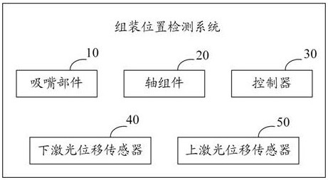
[0052] refer to figure 1 , figure 1 It is a schematic diagram of the functional modules of the first embodiment of the assembly position detection system of the present invention. The assembly position detection system includes: a nozzle part 10, a shaft assembly 20, a controller 30, a lower laser displacement sensor 40 and an upper laser displacement sensor 50;

[0053] The suction nozzle part 10 is used for suctioning the screen to be assembled.

[0054] It should be understood that the assembly position detection system in this embodiment is used to find a suitable assembly position, specifically, it can detect the assembly position of a glasses module. The glasses module is divided into a screen and a lens barrel. In this embodiment, , the screen that needs to be assembled is called the screen to be assembled, ...


PUM


Abstract

The invention relates to the technical field of module assembly, and discloses an assembly position detection system and method. The assembly position detection system includes: absorbing the screen to be assembled through a suction nozzle part, moving each part through a shaft assembly, and using a lower laser The displacement sensor measures the height of the screen to be assembled, and the upper laser sensor measures the height of the lens barrel to be assembled, and calculates the target axis corresponding to the shaft assembly when the screen to be assembled and the lens barrel to be assembled are at the starting position of assembly according to various data in the detection process Component position, so that module assembly is performed according to the target shaft component position, which is convenient for finding a suitable assembly position, thereby improving assembly efficiency.

Description

technical field [0001] The invention relates to the technical field of module assembly, in particular to an assembly position detection system and method. Background technique [0002] The glasses module in the VR glasses is divided into a screen and a lens barrel. When assembling the screen and the lens barrel, it is necessary to find a suitable assembly position to assemble the screen and the lens barrel. However, with the current technology, the way to determine the assembly position is more complicated and the accuracy is lower. [0003] The above content is only used to assist in understanding the technical solution of the present invention, and does not mean that the above content is recognized as [0004] current technology. Contents of the invention [0005] The main purpose of the present invention is to provide an assembly position detection system and method, aiming at solving the technical problem in the prior art that it is difficult to find a suitable assem...

Claims


Application Information

Patent Timeline
Patent Type & Authority Patents(China)
IPC IPC(8): G01B11/02H05K13/08
CPCG01B11/02H05K13/081
Inventor 李伟良刘玉竹邢方超徐朋涛
Owner GOERTEK OPTICAL TECH CO LTD
Features
  • R&D
  • Intellectual Property
  • Life Sciences
  • Materials
  • Tech Scout
  • Unparalleled Data Quality
  • Higher Quality Content
  • 60% Fewer Hallucinations
Learn More