
Hydraulic static leveling instrument with automatic exhaust function

A technology of static level and automatic exhaust, which is applied in the direction of equal hydrostatic pressure, and can solve the problems of not being able to obtain the vertical height of the level, troublesome replacement of water-proof and breathable membranes, and difficulty in adjusting the exhaust speed.

Pending Publication Date: 2020-10-23
HUNAN ZHONGDA CONSTR ENG TESTING TECH +1
View PDF4 Cites 4 Cited by
  • Summary
  • Abstract
  • Description
  • Claims
  • Application Information

AI Technical Summary

Problems solved by technology

If gas is generated in the hydraulic static level and is not discharged in time, so that it accumulates in the liquid chamber of the static level instrument, it will affect the measurement of water pressure, and the real vertical height of the level cannot be obtained, not only It affects the accuracy of the level gauge, and it is impossible to understand the safety hazards of the measured buildings in time
The current hydraulic static level needs to be manually exhausted before each measurement, which is troublesome and time-consuming. For example, the patent "CN201920993097-a hydraulic static level with automatic air bubble removal" is published. developed a hydraulic static level that automatically exhausts air bubbles. However, it needs to use expanded polytetrafluoroethylene as a waterproof and breathable layer. The material of the water-proof and breathable film needs to be replaced (because the exhaust speed of PTFE is not fast enough), and the replacement operation of the water-proof and breathable film is troublesome, it is difficult to adjust the exhaust speed of liquids with different bubbles, and the life of the material not long enough

Method used


Image

  • Hydraulic static leveling instrument with automatic exhaust function
  • Hydraulic static leveling instrument with automatic exhaust function

Examples


Embodiment Construction

[0025] In order to make the above objects, features and advantages of the present invention more comprehensible, specific implementations of the present invention will be described in detail below in conjunction with the accompanying drawings. In the following description, numerous specific details are set forth in order to provide a thorough understanding of the present invention. However, the present invention can be implemented in many other ways different from those described here, and those skilled in the art can make similar improvements without departing from the connotation of the present invention, so the present invention is not limited by the specific implementations disclosed below.

[0026] In the description of the present invention, it should be noted that unless otherwise specified and limited, the terms "connected" and "connected" should be understood in a broad sense, for example, it can be a fixed connection, a detachable connection, or an integral Ground co...


PUM


Abstract

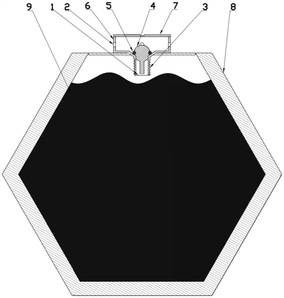
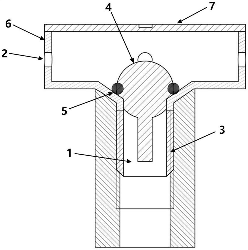
The invention discloses a hydraulic static leveling instrument with an automatic exhaust function. The leveling instrument is connected with an automatic exhaust valve; the automatic exhaust valve comprises a valve shell, an exhaust valve upper cover, a sealing ring and a small ball with a stabilizing rod; the valve shell is detachably connected with the exhaust valve upper cover; an air outlet isformed in the upper part of the valve shell; the lower part of the valve shell is provided with a hollow pipe which is connected with the liquid level of the inner liquid of the hydraulic static leveling instrument; an air inlet in the bottom of the hollow pipe is connnected with the air outlet through a cavity in the valve shell, the sealing ring is fixed to a funnel-shaped slope at the upper end of the hollow pipe, and the small ball with the stabilizing rod enables the stabilizing rod to be placed in the hollow pipe so that the small ball is tightly attached to the sealing ring. The devicecan automatically discharge a gas in the leveling instrument, is efficient and practical, can reduce measurement errors, greatly improves measurement precision of the static leveling instrument, andis convenient to operate, simple in structure and convenient to use.

Description

technical field [0001] The invention belongs to the technical field of hydraulic detection, in particular to an automatic exhaust device for a static level. Background technique [0002] The hydraulic static level is a high-precision liquid level measuring instrument based on the principle of a connecting device, which is suitable for detection occasions requiring high precision vertical displacement or settlement deformation. The pressure of the liquid in the level acts on the sensor, and the vertical height of the level is analyzed through the sensor, so as to understand and analyze the problem of settlement. If gas is generated in the hydraulic static level and is not discharged in time, so that it accumulates in the liquid chamber of the static level instrument, it will affect the measurement of water pressure, and the real vertical height of the level cannot be obtained, not only The accuracy of the level is affected, and the safety hazards of the measured buildings ca...

Claims


Application Information

Patent Timeline
IPC IPC(8): G01C5/04
CPCG01C5/04
Inventor 尹小波尹堃戴宏亮
Owner HUNAN ZHONGDA CONSTR ENG TESTING TECH
Learn More