Liquid crystal display device

A technology of liquid crystal display device and liquid crystal layer, which is applied in static indicators, nonlinear optics, instruments, etc., can solve the problem of inability to meet the wide and narrow viewing angle partition display and other problems

Active Publication Date: 2020-10-23
KUSN INFOVISION OPTOELECTRONICS
View PDF3 Cites 3 Cited by
  • Summary
  • Abstract
  • Description
  • Claims
  • Application Information

AI Technical Summary

Problems solved by technology

[0004] However, current liquid crystal display devices generally can only achieve wide viewing angles or narrow v

Method used


Image

  • Liquid crystal display device
  • Liquid crystal display device
  • Liquid crystal display device

Examples


no. 1 example

[0034] figure 1 It is a schematic structural diagram of the liquid crystal display device according to the first embodiment of the present invention. Please refer to figure 1 The liquid crystal display device of the first embodiment includes a display panel 10 and a dimmer 30, and the dimmer 30 is arranged on one side of the display panel 10. Specifically, in this embodiment, the dimmer 30 is disposed outside the display panel 10 .

[0035] In this embodiment, the display panel 10 is a liquid crystal display panel (LCD), which includes a first substrate 102 , a second substrate 104 and a first liquid crystal layer 106 disposed between the first substrate 102 and the second substrate 104 . It can be understood that the display panel 10 can also be other types of display panels, such as OLED (Light Emitting Diode Display Panel). Specifically, the first substrate 102 can be an array substrate, and the second substrate 104 can be a color filter substrate. More specifically, th...

no. 2 example

[0050] Figure 12 It is a schematic structural diagram of a liquid crystal display device according to the second embodiment of the present invention. Please refer to Figure 12 The liquid crystal display device of the second embodiment of the present invention is similar in structure to the liquid crystal display device of the first embodiment. On the side of the fourth substrate 320 away from the upper common electrode 322 .

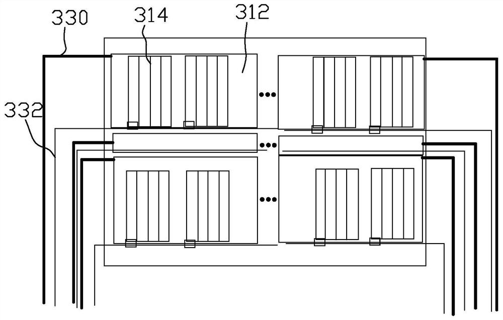
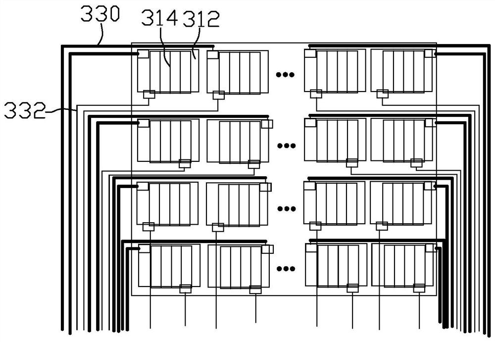
[0051] Specifically, the touch component 70 includes touch electrodes, and the touch electrodes include a plurality of driving electrodes (TX) distributed laterally and a plurality of receiving electrodes (RX) distributed vertically. The touch electrodes can be made of materials such as Mo (molybdenum), Al (aluminum), IZO (indium zinc oxide) or ITO (indium tin oxide).

[0052] The corresponding area of ​​the liquid crystal display device can be freely selected through the touch component 70, so as to realize the free switching of the display mode of...

no. 3 example

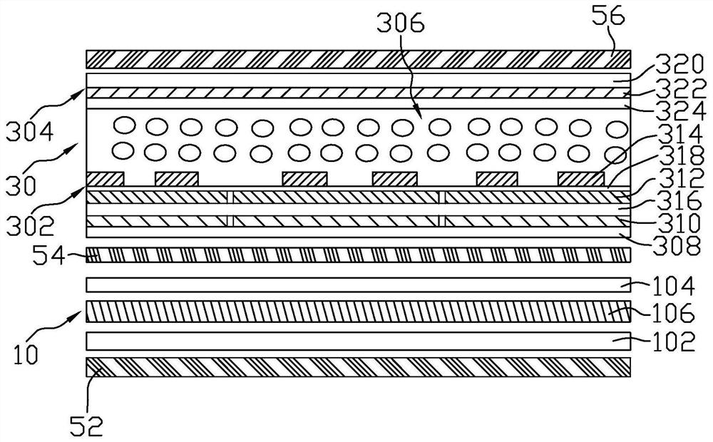
[0056] Figure 13 It is a schematic structural diagram of a liquid crystal display device according to a third embodiment of the present invention. Please refer to Figure 13 The liquid crystal display device of this embodiment includes a display panel 10 and a dimmer 30, and the dimmer 30 is arranged on one side of the display panel 10. Specifically, in this embodiment, the dimmer 30 is disposed outside the display panel 10 .

[0057] In this embodiment, the display panel 10 is a liquid crystal display panel (LCD), and its structure is the same as that of the display panel 10 in the first embodiment, so it will not be repeated here.

[0058] In this embodiment, the dimmer 30 includes a third substrate 302, a fourth substrate 304, and a second liquid crystal layer 306 disposed between the third substrate 302 and the fourth substrate 304. In this embodiment, the second liquid crystal layer 306 is a positive liquid crystal, and the alignment direction of the alignment film (n...


PUM

PropertyMeasurementUnit
Thicknessaaaaaaaaaa

Abstract

The invention discloses a liquid crystal display device which comprises a display panel and a light modulator. The light modulator is arranged on one side of the display panel. The light modulator comprises a third base plate, a fourth base plate and a second liquid crystal layer arranged between the third base plate and the fourth base plate. The third base plate comprises a third substrate, a lower common electrode and a pixel electrode, wherein the lower common electrode and the pixel electrode are arranged in an insulated and spaced mode, the lower common electrode is divided into a plurality of sub lower common electrodes, and the pixel electrode is divided into a plurality of sub pixel electrodes; and the fourth base plate comprises a fourth substrate and an upper common electrode, wherein the upper common electrode is arranged on the fourth substrate body. In the liquid crystal display device, the lower common electrode and the pixel electrode are divided into a plurality of blocks, or the upper common electrode and the pixel electrode are divided into a plurality of blocks, so that pressure difference region control between the pixel electrode and the upper common electrodeof the liquid crystal display device can be realized, and regional control of wide and narrow viewing angle display is realized.

Description

technical field [0001] The invention relates to the technical field of liquid crystal display, in particular to a liquid crystal display device. Background technique [0002] Liquid crystal display devices have the advantages of good image quality, small size, light weight, low driving voltage, low power consumption, no radiation and relatively low manufacturing cost, and they occupy a dominant position in the field of flat panel display. [0003] With the continuous advancement of liquid crystal display technology, the viewing angle of the display has been expanded from about 120° to more than 160°. While enjoying the visual experience brought by the large viewing angle, people also hope to effectively protect commercial secrets and personal privacy. In order to avoid commercial loss or embarrassment caused by leakage of screen information. Therefore, in addition to the wide viewing angle, the display device is also required to have the function of switching between the wi...

Claims


Application Information

Patent Timeline
IPC IPC(8): G02F1/1343G02F1/13G02F1/133G02F1/1333G02F1/1335G02F1/1347
CPCG02F1/134309G02F1/1323G02F1/13306G02F1/13338G02F1/133528G02F1/1347
Inventor 钟德镇姜丽梅沈家军
Owner KUSN INFOVISION OPTOELECTRONICS
Why Eureka
Try Eureka