
Projection lighting device and projection equipment

A lighting device and projection technology, applied in the field of projection display, can solve the problem of wasting light energy and the like

Pending Publication Date: 2020-10-23
HANGZHOU KOTI OPTICAL TECH
View PDF0 Cites 1 Cited by
  • Summary
  • Abstract
  • Description
  • Claims
  • Application Information

AI Technical Summary

Problems solved by technology

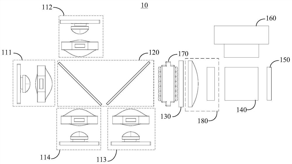
[0004] The object of the present invention is to provide a projection lighting device and projection equipment to improve the problem of wasting light energy in traditional projection lighting devices

Method used


Image

  • Projection lighting device and projection equipment
  • Projection lighting device and projection equipment
  • Projection lighting device and projection equipment

Examples


Embodiment Construction

[0056] The technical solutions in the embodiments of the present application will be clearly and completely described below in conjunction with the drawings in the embodiments of the present application.

[0057] In the description of this application, it should be noted that the orientation or positional relationship indicated by the terms "inner", "outer", etc. is based on the orientation or positional relationship shown in the drawings, or the usual placement of the application product when it is used. Orientation or positional relationship is only for the convenience of describing the present application and simplifying the description, and does not indicate or imply that the referred device or element must have a specific orientation, be constructed and operated in a specific orientation, and thus should not be construed as limiting the present application. In addition, the terms "first", "second", etc. are only used for distinguishing descriptions, and should not be const...


PUM


Abstract

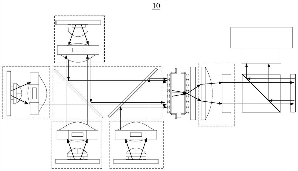
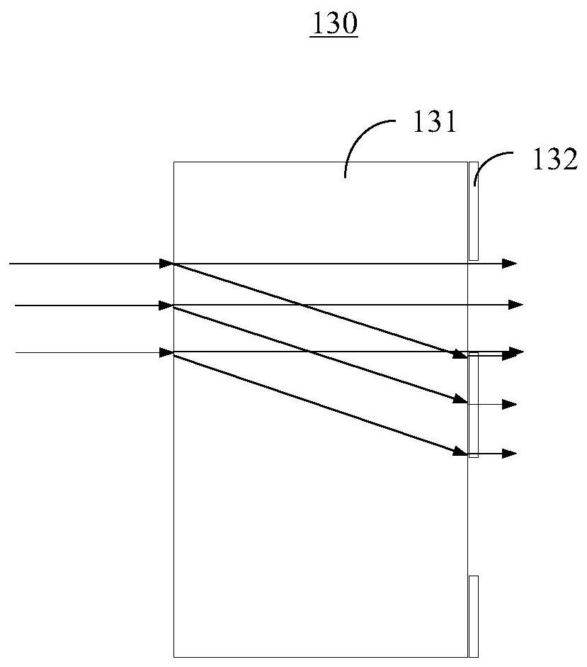
The invention discloses a projection lighting device and projection equipment. The projection lighting device comprises a plurality of light source devices, a light combining device, a polarized lightconversion device, a light beam control device, a reflection imaging device and a projection device, wherein the light combining device is used for combining light beams emitted by a plurality of light source devices to obtain a main light beam, the polarized light conversion device is used for converting the main light beam into a polarized light beam, the light beam control device is used for transmitting the polarized light beam to the reflection imaging device, the reflection imaging device reflects the polarized light beam to obtain a reflected light beam with the image information, andthe light beam control device is further used for transmitting the reflected light beams to the projection device for corresponding projection. The projection lighting device is advantaged in that thepolarized light conversion device is arranged in the projection lighting device, and the main light beam emitted by the light source device is converted into the polarized light beam, so the reflection imaging device can perform reflection imaging by utilizing all the polarized light beams, and the light energy utilization rate of the projection lighting device can be greatly improved.

Description

technical field [0001] The present invention relates to the field of projection display, in particular to a projection lighting device and projection equipment. Background technique [0002] Since the 1950s, projection technology has continuously made breakthroughs in foreign developed countries. From CRT projection technology to DLP technology, the products have been continuously improved and gradually penetrated into daily life. It has been widely disseminated around the world, and China has also been inspired to start a rapid development process. During the period, the continuous introduction of policies will further expand the demand of the projection industry, and the shipment volume of the projection market will continue to increase. [0003] The traditional projection lighting device will waste a lot of light energy during the projection process, and the utilization rate of light energy is not high, resulting in poor final imaging effect. Contents of the invention ...

Claims


Application Information

Patent Timeline
Patent Type & Authority Applications(China)
IPC IPC(8): G03B21/20
CPCG03B21/2013G03B21/2066G03B21/2073
Inventor 牛建帅李有森金波陈新明刘书墨
Owner HANGZHOU KOTI OPTICAL TECH
Learn More