Supercharge Your Innovation With Domain-Expert AI Agents!

Single-camera multi-view calibration method based on robot

A calibration method and robot technology, applied in the field of robot vision, can solve problems such as high cost, high cost, and inapplicability for large-scale promotion

Pending Publication Date: 2020-10-23
FOSHAN LONGSHEN ROBOT
View PDF12 Cites 0 Cited by
  • Summary
  • Abstract
  • Description
  • Claims
  • Application Information

AI Technical Summary

Problems solved by technology

The difficulty of calibrating a single camera in multiple fields of view is that it is impossible to use traditional methods to stitch images in a unified coordinate system when each field of view does not overlap.
[0003] In the prior art, multiple cameras are used to calibrate the inventions and creations in different fields of view, and the cost is relatively high. For example, the high-precision large-field-of-view machine vision measurement and calibration device and method with the publication number CN109099883A are used for high-precision large-scale The measurement and calibration of the field of view is to shoot with multiple cameras, and then stitch the shooting fields of multiple cameras into a large field of view, which is expensive and not suitable for large-scale promotion

Method used


Image

  • Single-camera multi-view calibration method based on robot

Examples


Embodiment 1

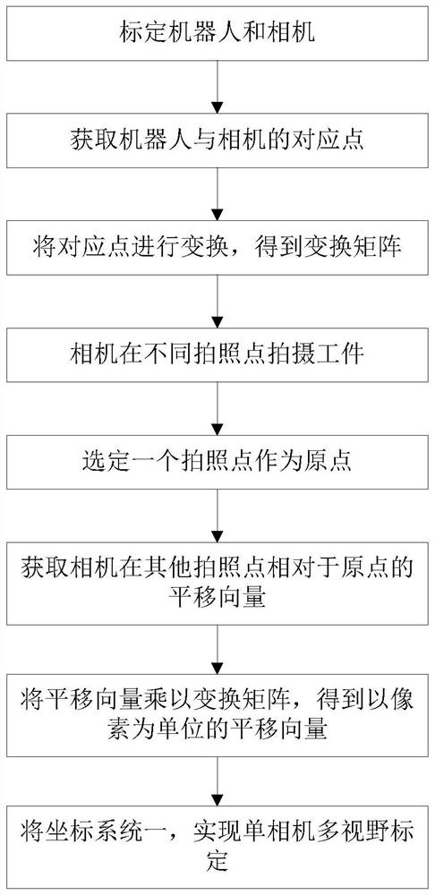
[0034] Such as figure 1 As shown, a robot-based single-camera multi-view calibration method includes the following steps:

[0035] S1: Calibrate the robot and camera;

[0036] S2: Obtain the corresponding points between the robot and the camera;

[0037] S3: Transform the corresponding points to obtain the transformation matrix T;

[0038] S4: The camera shoots the workpiece at different photo points;

[0039] S5: select a photographing point as the origin;

[0040] S6: Obtain the translation vector T of the camera at other photographing points relative to the origin through the robot i ;

[0041] S7: Multiply the translation vector by the transformation matrix to obtain the translation vector in pixels

[0042] S8: Use coordinate system 1 to realize single-camera multi-view calibration.

[0043] More specifically, in step S1, the camera plane and the robot base plane are kept parallel to the working plane.

[0044] More specifically, in step S2, at least three corre...

Embodiment 2

[0053] A robot-based single-camera multi-view calibration method is basically the same as the robot-based single-camera multi-view calibration method described in Embodiment 1, the difference being:

[0054] More specifically, in step S4, the camera is fixed at a fixed position, and the manipulator of the robot moves the workpiece to take pictures, so that the camera can take pictures of the workpiece at different photographing points.

[0055] More specifically, in step S6, the obtained translation vector needs to be multiplied by a coefficient -1.


PUM


Abstract

The invention provides a single-camera multi-view calibration method based on a robot. The single-camera multi-view calibration method comprises the following steps: S1, calibrating the robot and a camera; s2, obtaining corresponding points of the robot and the camera; s3, transforming the corresponding points to obtain a transformation matrix T; s4, the camera shoots the workpiece at different shooting points; s5, selecting a photographing point as an original point; s6, acquiring a translation vector Ti of the camera at other photographing points relative to the original point through the robot; s7, multiplying the translation vector by the transformation matrix to obtain a translation vector taking a pixel as a unit; and S8, unifying coordinate systems to realize single-camera multi-view calibration. According to the single-camera multi-view calibration method based on the robot, coordinate systems are unified, under the condition that the view fields of shot objects do not coincide, a single camera is used for conducting measurement, positioning, scene splicing and the like on a workpiece, and the problem that multiple cameras are needed during multi-view calibration is solved.

Description

technical field [0001] The present invention relates to the technical field of robot vision, and more specifically, to a robot-based single-camera multi-view calibration method. Background technique [0002] With the increasing application of machine vision, the demand for camera calibration in multiple fields of view is getting higher and higher. The use of a single camera can reduce costs, and the coordinate system of a single camera with different fields of view can be applied to large-format high-precision positioning and measurement And scene stitching and other applications. The difficulty of calibrating a single camera in multiple fields of view is that it is impossible to use traditional methods to stitch images in a unified coordinate system when each field of view does not overlap. [0003] In the prior art, multiple cameras are used to calibrate in different fields of view, and the cost is relatively high. For example, the high-precision large-field-of-view machi...

Claims


Application Information

Patent Timeline
IPC IPC(8): G06T7/80
CPCG06T7/80Y02P90/02
Inventor 汪良红王辉陈新苏鑫盛国强
Owner FOSHAN LONGSHEN ROBOT
Features
  • R&D
  • Intellectual Property
  • Life Sciences
  • Materials
  • Tech Scout
  • Unparalleled Data Quality
  • Higher Quality Content
  • 60% Fewer Hallucinations
Learn More