
Drive device for an aircraft with electric machine and cooling device

A driving device and cooling mechanism technology, applied in electromechanical devices, cooling/ventilation devices, cooling systems of power devices, etc., can solve problems such as consumption

Pending Publication Date: 2020-10-23
ROLLS ROYCE DEUT LTD & CO KG
View PDF0 Cites 0 Cited by
  • Summary
  • Abstract
  • Description
  • Claims
  • Application Information

AI Technical Summary

Problems solved by technology

But this leads to a costly design solution in several ways

Method used


Image

  • Drive device for an aircraft with electric machine and cooling device

Examples


Embodiment Construction

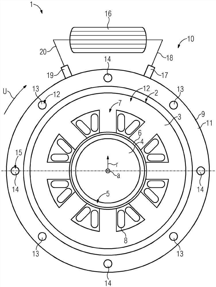
[0025] The figure shows a drive device 1 according to an embodiment of the invention in a cutaway illustration. The drive device 1 includes an electric motor 2 . The motor 2 further includes a stator 3 and a rotor 4 . In this case, the rotor 4 is embodied internally and rotatably relative to the stator 3 . An air gap 5 is formed between the stator 3 and the rotor 4 . A gap tube 6 is present in the air gap 5 , which can be hollow-cylindrical. The stator 3 of the electric machine 2 has a plate pack 7 on which the coils 8 of the winding of the electric machine 2 are arranged. The electric machine 2 can in particular be designed as a permanently excited synchronous machine with surface magnets. Here, surface magnets or permanent magnets are arranged on the rotor 4 . Furthermore, the electric machine 2 includes a housing 9 .

[0026] Furthermore, the drive device 1 includes a cooling device 10 . The cooling device 10 includes an internal heat exchanger 11 for transferring he...


PUM


Abstract

The invention relates to a drive device (1) for an aircraft, comprising: an electric machine (2) with a stator (3) and a rotor (4) and a cooling device (10) for cooling the electric machine (2), the cooling device (10) having an encapsulated first cooling region (12), in which a first cooling liquid for cooling the stator (3) and / or the rotor (4) is disposed, the cooling device (10) having a second cooling region (15), which is separate from the first cooling region (12) and in which the second liquid is disposed, and the cooling device (10) having an internal heat exchanger (11) for transmitting heat from the first cooling liquid to the second cooling liquid.

Description

technical field [0001] The invention relates to a drive for an aircraft, comprising an electric machine with a stator and a rotor, and a cooling mechanism for cooling the electric machine. Background technique [0002] Aircraft are known from the prior art which are operated with electric drives. Such a drive includes an electric motor and a cooling device for cooling the electric motor. In this case, the electric machine is cooled directly or indirectly, in particular when a combustible liquid is used. The combustible liquids essentially present a potential fire hazard with regard to the fuel load (brand last) of the liquids used and the design used. After the combustible liquid used as cooling liquid has absorbed the heat inside the electric machine, it is cooled outside the electric machine to the desired operating temperature by means of an externally installed heat exchanger. [0003] In the aeronautics industry, it is especially necessary to assess the extent to whi...

Claims


Application Information

Patent Timeline
Patent Type & Authority Applications(China)
IPC IPC(8): B64D27/24H02K3/24H02K5/20H02K9/19
CPCH02K3/24H02K9/19B64D27/24Y02T50/60H02K5/203H02K1/20H02K9/14
Inventor H·维齐斯克R·戈拉吉
Owner ROLLS ROYCE DEUT LTD & CO KG
Learn More