Speaker device

A loudspeaker and exciter technology, applied in the field of loudspeaker devices, can solve problems such as damage to the design of the vibrating plate

Active Publication Date: 2020-10-23
ASAHI GLASS CO LTD
View PDF10 Cites 1 Cited by
  • Summary
  • Abstract
  • Description
  • Claims
  • Application Information

AI Technical Summary

Problems solved by technology

In this method, although the vibration of the sound signal can be efficiently transmitted to the vibrating plate, the vibrating plate has a problem of impairing the design of the vibrating

Method used


Image

  • Speaker device
  • Speaker device
  • Speaker device

Examples


Embodiment

[0159] Hereinafter, although an Example is given and this invention is demonstrated concretely, this invention is not limited to these descriptions.

[0160]

[0161] One side of a pair of substrates was used as substrate 1, and a glass substrate A of 300 mm × 300 mm × 0.5 mm was prepared. On the surface of the substrate, silicone oil with a viscosity coefficient of 3000 mPa·s (Shin-Etsu Chemical Industry; KF-96) as a liquid layer. And the other one of a pair of board|substrates was used as the board|substrate 2, and the glass substrate B of 300 mmx300 mmx0.5 mm was adhered to the glass substrate A so that the liquid thickness might become 3 micrometers. Thus, a diaphragm structure having two glass substrates and a liquid layer was obtained.

[0162] The compositions (% by mass) and physical property values ​​of the glass substrate A and the glass substrate B are shown below.

[0163] (Glass substrate A) SiO 2 : 61.5%, Al 2 o 3 : 20%, B 2 o 3 : 1.5%, MgO: 5.5%, CaO: 4...


PUM

PropertyMeasurementUnit
Thicknessaaaaaaaaaa
Viscosity coefficientaaaaaaaaaa
Surface tensionaaaaaaaaaa

Abstract

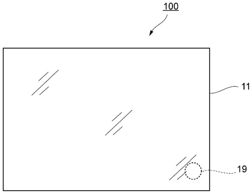
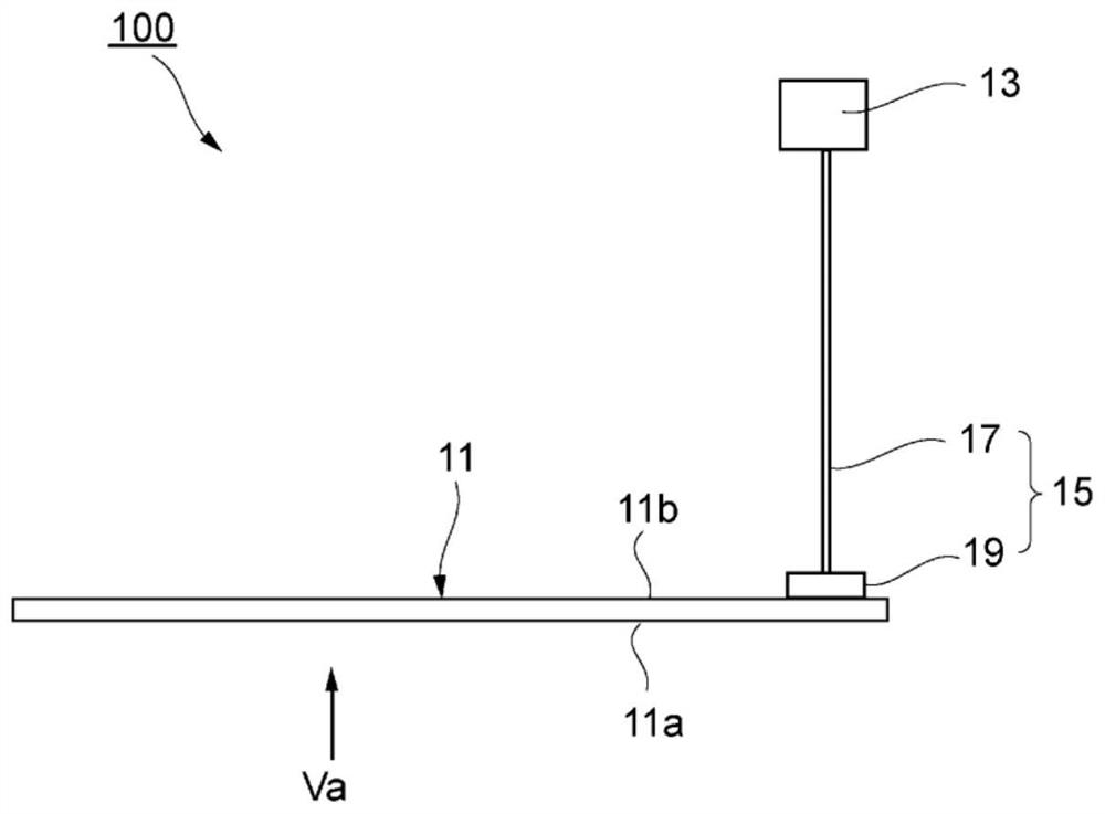
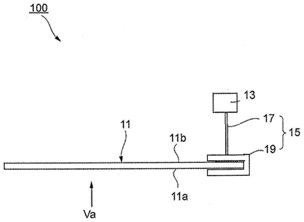
A speaker device is provided with a diaphragm (11); an exciter (13) for generating vibration in accordance with an inputted electric signal; and a vibration transmission unit (15), provided between the diaphragm (11) and the exciter (13), for transmitting vibration from the exciter (13) to the diaphragm (11). The loss factor of the diaphragm (11) at 25 DEG C is 1*10-2 or greater, and the specificelastic modulus of the vibration transmission unit (15) is 20 mm2/s2 or greater.

Description

technical field [0001] The present invention relates to a speaker device that vibrates a diaphragm to generate sound. Background technique [0002] Generally, there is known a technique for generating sound from a diaphragm by vibrating a diaphragm with an exciter having a vibrating portion (for example, refer to Patent Document 1). Patent Document 1 describes a configuration in which a vibration speaker for converting an audio signal into vibration is provided on the lower surface of the ceiling, and a vibration plate is provided in direct contact with the vibration transmission surface of the vibration speaker. According to this configuration, the vibration speaker excites the diaphragm to generate sound corresponding to the sound vibration from the diaphragm. [0003] Patent Document 1: Japanese Patent Laid-Open No. 2016-23000 [0004] In a speaker device having such a diaphragm, in recent years, it has been proposed to use transparent materials such as glass plates and...

Claims


Application Information

Patent Timeline
IPC IPC(8): H04R7/04H04R7/02H04R7/08H04R7/10
CPCH04R7/06H04R7/122H04R9/025H04R9/04H04R9/06H04R7/10H04R7/125H04R7/18H04R31/003H04R2307/023H04R2440/05H04R2499/15H04R1/2834
Inventor 秋山顺樱井研人
Owner ASAHI GLASS CO LTD
Why Eureka
Try Eureka