Supercharge Your Innovation With Domain-Expert AI Agents!

Equipment for disc punching

A kind of equipment and disc technology, applied in the field of disc punching equipment, can solve the problem that it is difficult to accurately control plastic discs

Active Publication Date: 2020-10-27
南通新冯精密机械有限公司
View PDF5 Cites 0 Cited by
  • Summary
  • Abstract
  • Description
  • Claims
  • Application Information

AI Technical Summary

Problems solved by technology

[0004] In order to overcome the shortcomings in the prior art that it is difficult to accurately control the rotation of the plastic disc and that people need to hold the plastic disc in the stamping machine continuously, the technical problem is to provide a method that can accurately control the rotation of the plastic disc and can automatically unload it. material, and then achieve effective punching equipment for disc punching

Method used


Image

  • Equipment for disc punching
  • Equipment for disc punching
  • Equipment for disc punching

Examples


Embodiment 1

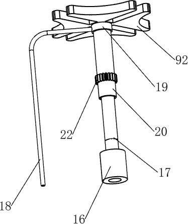
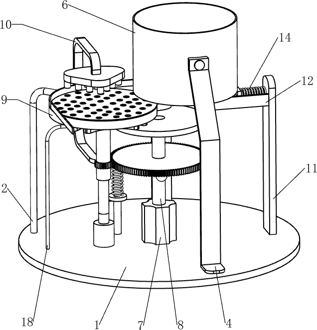
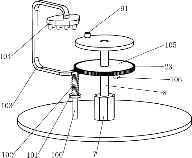
[0022] A device for punching holes in discs, such as Figure 1-6 As shown, it includes a base 1, a first support rod 2, an arc-shaped limit plate 3, a first support seat 4, a second support seat 5, a circular plate box 6, a servo motor 7, a first rotating shaft 8, and an intermittent rotation mechanism. 9. The punching mechanism 10, the fourth support rod 18 and the second bearing seat 19, the left side of the top of the base 1 is fixedly connected with the first support rod 2, the upper end of the first support rod 2 is provided with an arc-shaped limit plate 3, the base 1 The front side of the top is fixedly connected with the first support seat 4, and the rear side of the top of the base 1 is fixedly connected with the second support seat 5, and a circular plate box 6 is connected by bolts between the second support seat 5 and the top of the first support seat 4. 1. A servo motor 7 is installed in the middle of the top. The top of the output shaft of the servo motor 7 is pr...

Embodiment 2

[0029] On the basis of Example 1, such as figure 1 and Figure 3-6 As shown, it also includes a support plate 11, a slide rail 12, a push plate 13, a second spring 14 and a second extrusion block 15, the right side of the top of the base 1 is fixedly connected with the support plate 11, and the left side of the support plate 11 is provided with Slide rail 12, sliding type is provided with push plate 13 in slide rail 12, is connected with second spring 14 between push plate 13 and support plate 11, is provided with the second extruding block 15 on the outer side of carrying plate 93, and the second extruding block 15 cooperates with push pedal 13.

[0030] Also include first bearing seat 16, second rotating shaft 17, ring rotating shaft 20, driving lever 21, first gear 22 and second gear 23, first bearing seat 16 is installed on the left side of base 1 top, first bearing seat 16 The inner rotation type is provided with a second rotating shaft 17, the upper part of the second ro...


PUM


Abstract

The invention relates to punching equipment, in particular to equipment for disc punching. The technical problem is to provide the equipment for disc punching, which can accurately control rotation ofa plastic disc and conduct automatic discharging, thereby achieving effective punching. The equipment for disc punching comprises a base which is a hard circular plate; a first supporting rod which is fixedly connected to one side of the top of the base; an arc-shaped limiting plate which is arranged at the upper end of the first supporting rod; and a first supporting seat which is fixedly connected to one side of the top of the base. According to the equipment for disc punching, the effects of accurately controlling the rotation of the plastic disc, automatically discharging and then achieving effective punching are achieved, and through cooperation of a second extrusion block and a push plate, the push plate can continuously push the disc at the bottom of a circular plate box to the position above a sheet, thereby realizing the automatic discharging.

Description

technical field [0001] The invention relates to a punching device, in particular to a device for punching a disc. Background technique [0002] In modern industry, plastic discs can be used as accessories. Some plastic toys or some machines require stamped and punched plastic discs. In existing factories, these plastic discs are stamped and punched. When making holes, workers usually hold a plastic disc, put one of the corners of the plastic disc into the punching machine, and the punching machine punches it, then rotates the plastic disc 90 degrees, and puts it in again. Holes are punched in the stamping machine, so the plastic disc can be punched four times. However, this punching and punching method has high requirements for workers, and it is necessary to precisely control the rotation of the plastic disc. New workers It may be difficult to grasp the angle of rotation, and workers need to put the plastic discs into the stamping machine one by one, which is very troubles...

Claims


Application Information

Patent Timeline
IPC IPC(8): B26F1/02B26F1/14B26D5/22B26D5/08B26D7/06B26D7/18
CPCB26F1/02B26F1/14B26D5/22B26D5/083B26D7/06B26D7/0608B26D7/1818
Inventor 肖辉
Owner 南通新冯精密机械有限公司
Features
  • R&D
  • Intellectual Property
  • Life Sciences
  • Materials
  • Tech Scout
  • Unparalleled Data Quality
  • Higher Quality Content
  • 60% Fewer Hallucinations
Learn More