Al technical title is built by PatSnap Al team. It summarizes the technical point description of the patent document.
A technology of automatic spraying and equipment, applied in the direction of spraying device, etc., can solve the problems of difficulty and complexity of product width, thickness, dimensional accuracy, plate shape and surface quality control, complicated structure of spraying equipment, complicated and huge rolling mill equipment, etc. The effect of labor cost, stable work performance and high degree of automation
Inactive Publication Date: 2018-04-27
董丽芳
View PDF0 Cites 11 Cited by
Summary
Abstract
Description
Claims
Application Information
AI Technical Summary
This helps you quickly interpret patents by identifying the three key elements:
Problems solved by technology
Method used
Benefits of technology
Problems solved by technology
In addition, the plate also has the following production characteristics: (1) The plate is rolled out with flat rolls, so it is relatively simple and easy to change product specifications, easy to adjust and operate, and easy to realize comprehensive computer control and automatic production; (2) The shape of the plate is simple, It can be produced in coils and is used in the largest amount in the national economy, so it must and can realize high-speed continuous rolling production; (3) Due to the large width-to-thickness ratio and surface area, the rolling pressure in production is very high, up to several hundred Tens of thousands to tens of millions of newtons, so the rolling mill equipment is complex and huge, and it becomes very difficult and complicated to control the dimensional accuracy of the product width and thickness, and the shape and surface quality
[0003] In the plate production process, spraying equipment is usually required. The traditional spraying equipment has a complex structure, poor spraying effect, and low degree of automation.
Method used
Image
Click on the blue label to locate the original text in one second.
Reading with bidirectional positioning of images and text.
Examples
Embodiment Construction
[0020] The following will clearly and completely describe the technical solutions in the embodiments of the present invention with reference to the accompanying drawings in the embodiments of the present invention. Obviously, the described embodiments are only some, not all, embodiments of the present invention. Based on the embodiments of the present invention, all other embodiments obtained by persons of ordinary skill in the art without making creative efforts belong to the protection scope of the present invention.
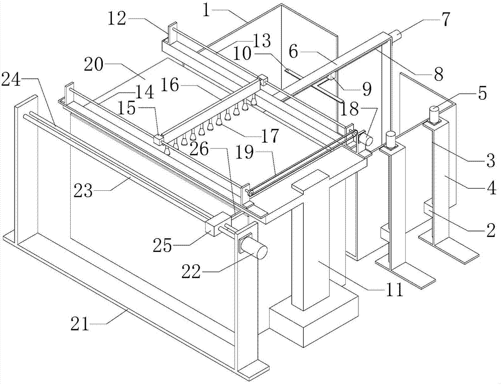
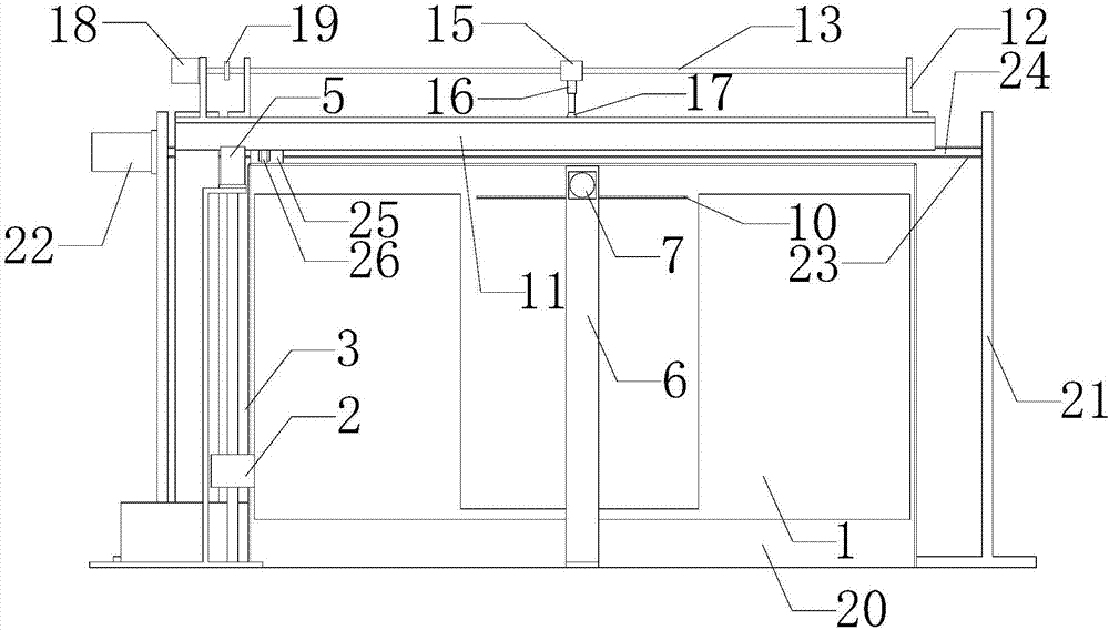
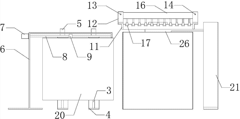
[0021] see Figure 1-3 , the present invention provides a technical solution: the sheet metal automatic spraying equipment includes a material box 1, the material box 1 is connected to the vertical screw rod 3 through the lifting slider 2, and the vertical screw rod 3 passes through the first Support 4 is fixedly connected with first motor 5, and the right side of described material box 1 is provided with second support 6, and the right side of described secon...
PUM
Abstract
The invention discloses a sheet metal automatic spraying equipment, which includes a material box, the material box is connected to a vertical screw rod through a lifting slider, and the vertical screw rod is fixedly connected to a first motor through a first bracket. One side of the large screw rod is provided with a large guide rod, and the large screw rod is connected to the unloading plate through a large slider, and the unloading plate is located above the spraying platform. The present invention has high degree of automation, easy operation, high work efficiency, and low energy consumption. The power source is provided by the first motor and the second motor, and the automatic feeding of the plate is realized by using the material box and the pushing plate as the execution parts, which saves labor costs. The third motor is used as the power source to drive the right screw rod and the left screw rod at the same time, and the spraying slider drives the nozzle to move along the surface of the plate. The working performance is stable and the spraying quality is high. The fourth motor drives the large screw rod to rotate, and then passes The large slider drives the unloading plate to translate along the surface of the spraying platform, and pushes the sprayed plate away from the spraying platform to realize automatic unloading.
Description
technical field [0001] The invention relates to the technical field of mechanical processing equipment, in particular to a sheet metal automatic spraying equipment. Background technique [0002] According to the thickness of the board, the board can be divided into thin board, medium board, thick board, extra thick board, and usually made into a flat rectangular building material board of standard size. The shape of the plate product is flat, the ratio of width to thickness is large, and the surface area per unit volume is also large. Products, metal structures, etc. are widely used; (2) can be cut, bent, stamped, welded, and made into various product components, flexible and convenient to use, and occupy an extremely important role in automobiles, aviation, shipbuilding, and tractor manufacturing. (3) It can be bent and welded into structural parts such as section steel, steel pipe, large I-beam, channel steel, etc. of various complex sections, so the plate plays an import...
Claims
Application Information
Patent Timeline
Application Date:The date an application was filed.
Publication Date:The date a patent or application was officially published.
First Publication Date:The earliest publication date of a patent with the same application number.
Issue Date:Publication date of the patent grant document.
PCT Entry Date:The Entry date of PCT National Phase.
Estimated Expiry Date:The statutory expiry date of a patent right according to the Patent Law, and it is the longest term of protection that the patent right can achieve without the termination of the patent right due to other reasons(Term extension factor has been taken into account ).
Invalid Date:Actual expiry date is based on effective date or publication date of legal transaction data of invalid patent.