Smashing and cleaning mechanism

A cleaning mechanism and rack technology, applied in the field of plastic processing, can solve the problems of low work efficiency, achieve the effect of improving work efficiency, shortening processing time, and strengthening cleaning effect

Inactive Publication Date: 2018-08-24
宁波隆锐机械制造有限公司
View PDF1 Cites 12 Cited by
  • Summary
  • Abstract
  • Description
  • Claims
  • Application Information

AI Technical Summary

Problems solved by technology

[0004] The present invention intends to provide a crushing and cleaning mechanism to solve the problem of low work efficiency caused by the intermittent work of waste plastic cleaning and crushing equipment in the prior art

Method used


Image

  • Smashing and cleaning mechanism
  • Smashing and cleaning mechanism

Examples


Embodiment Construction

[0023] Further detailed explanation through specific implementation mode below:

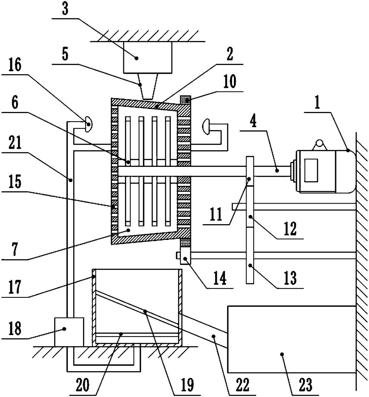
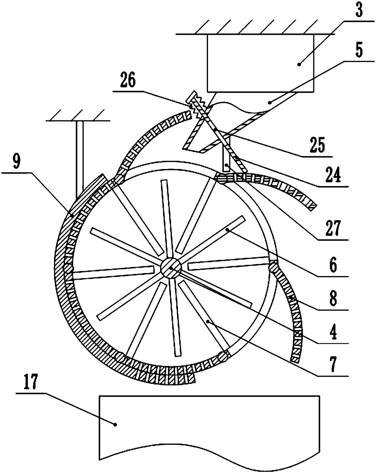
[0024] The reference signs in the drawings of the description include: motor 1, drum 2, storage bin 3, rotating shaft 4, discharge pipe 5, cutter 6, partition 7, rotating plate 8, arc-shaped baffle 9, ring gear 10 , the first gear 11, the second gear 12, the third gear 13, the fourth gear 14, the first through hole 15, the nozzle 16, the collection box 17, the water pump 18, the first screen 19, the second screen 20, the outlet Water pipe 21, feeding pipe 22, crushing tank 23, T-shaped slide plate 24, second through hole 25, spring 26, vertical bar 27.

[0025] This embodiment is basically as figure 1As shown, a crushing and cleaning mechanism includes a frame, and the frame is fixedly equipped with a motor 1, a rotating drum 2 and a storage bin 3, the output end of the motor 1 is fixedly connected with a rotating shaft 4, and the storage bin 3 is fixedly connected with a discharge Tube 5. The...


PUM


Abstract

The invention relates to the technical field of plastic processing, and particularly discloses a smashing and cleaning mechanism. The smashing and cleaning mechanism comprises a motor, a rotating drumand a storage bin, wherein the motor is connected with a rotating shaft, and the storage bin is connected with a discharge pipe. The rotating shaft is provided with a plurality of cutters for cuttingplastic, a plurality of rows of clapboards are connected with the inner wall of the rotating drum, the clapboards are provided with through grooves for the cutters to pass through, and openings are formed between the adjacent clapboards on the peripheral wall of the rotating drum. Rotating plates are hinged at the openings, torsion springs are installed at the hinging positions between the rotating plates and the rotating drum, and an arc-shaped baffle plate for abutting against the rotating plates is arranged beside the rotating drum. A plurality of first through holes are formed in the sidewall of the rotating drum, and a plurality of spray heads are installed at both ends of the rotating drum. The discharge pipe is slidingly connected with an inclined T-shaped sliding plate, the T-shaped sliding plate is provided with a second through hole, and a spring is connected between the T-shaped sliding plate and the outer wall of the discharge pipe. The rotating plates can abut against the T-shaped sliding plate, and a vertical rod capable of abutting against the rotating plates is connected to the outer wall of the discharge pipe. The smashing and cleaning mechanism can simultaneously clean and cut the plastic, the smashing and cleaning mechanism can work for a long time, and the efficiency is improved.

Description

technical field [0001] The invention relates to the technical field of plastic processing, and specifically discloses a crushing and cleaning mechanism. Background technique [0002] As the consumption of plastic products continues to increase, waste plastics also continue to increase. At present, my country's waste plastics are mainly plastic films, plastic yarns and woven products, foam plastics, plastic packaging boxes and containers, daily-use plastic products, plastic bags and agricultural mulch films. Improper disposal of these waste plastics will inevitably seriously pollute the environment and cause waste of resources. Therefore, these waste plastics need to be recycled and reused. [0003] The process of recycling waste plastics is mainly divided into the following steps: collection, sorting, crushing, cleaning, dehydration, drying, melting, and molding. The crushing and cleaning processes in the process are closely related to the quality of recycled plastics. Ther...

Claims


Application Information

Patent Timeline
Patent Type & Authority Applications(China)
IPC IPC(8): B29B17/00B29B17/04
CPCB29B17/00B29B17/04B29B2017/0015B29B2017/044Y02W30/52Y02W30/62
Inventor 李新平
Owner 宁波隆锐机械制造有限公司
Why Eureka
Try Eureka