
Material separation mechanism

A separation mechanism and material technology, applied in the direction of conveyors, conveyor objects, mechanical conveyors, etc., can solve the problem that the material distribution mechanism cannot meet the requirements of separating two materials at a time

Pending Publication Date: 2020-10-27
深圳市合利士智能装备有限公司
View PDF0 Cites 0 Cited by
  • Summary
  • Abstract
  • Description
  • Claims
  • Application Information

AI Technical Summary

Problems solved by technology

[0003] The main purpose of the present invention is to propose a material separation mechanism, which aims to solve the technical problem that the existing material distribution mechanism cannot meet the requirement of separating two materials at a time, and the direction of material distribution is parallel to the direction of incoming materials.

Method used


Image

  • Material separation mechanism
  • Material separation mechanism
  • Material separation mechanism

Examples


Embodiment Construction

[0017] The specific embodiments of the present invention will be further described below in conjunction with the accompanying drawings. It should be noted here that the descriptions of these embodiments are used to help understand the present invention, but are not intended to limit the present invention. In addition, the technical features involved in the various embodiments of the present invention described below may be combined with each other as long as they do not constitute a conflict with each other.

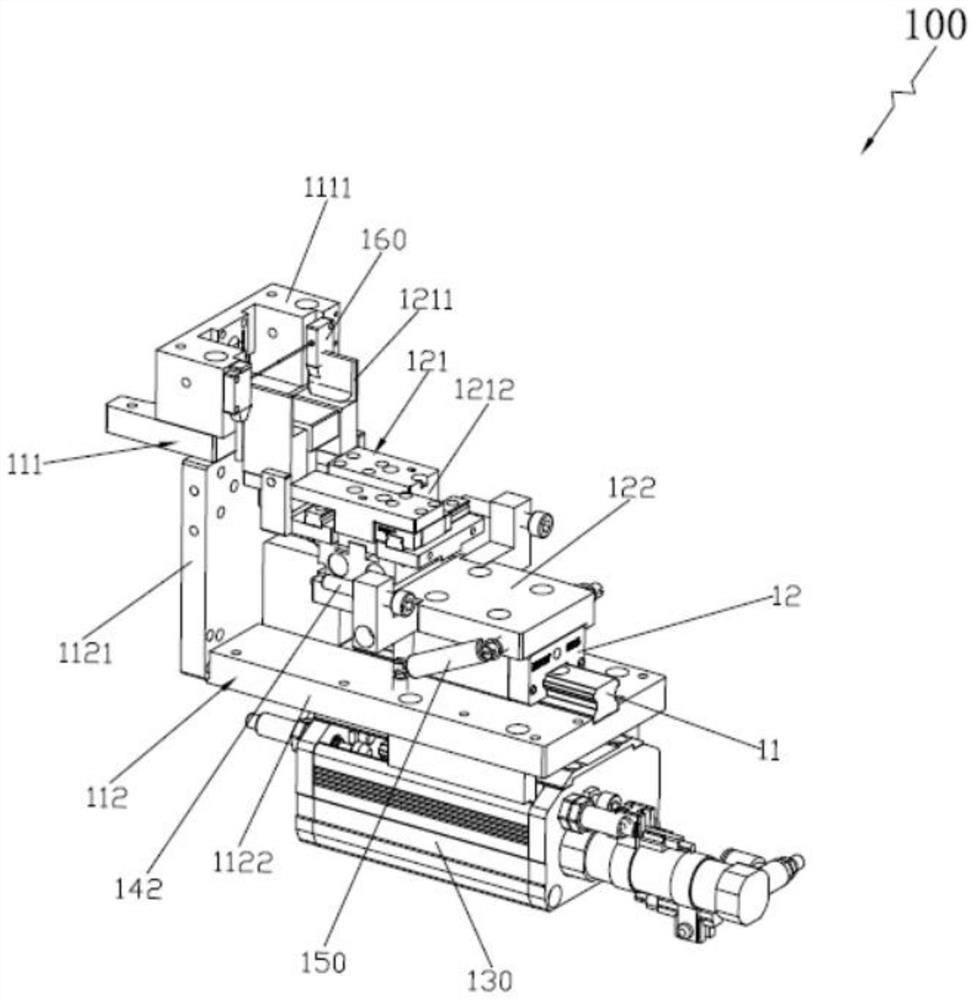
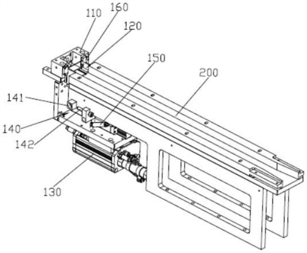
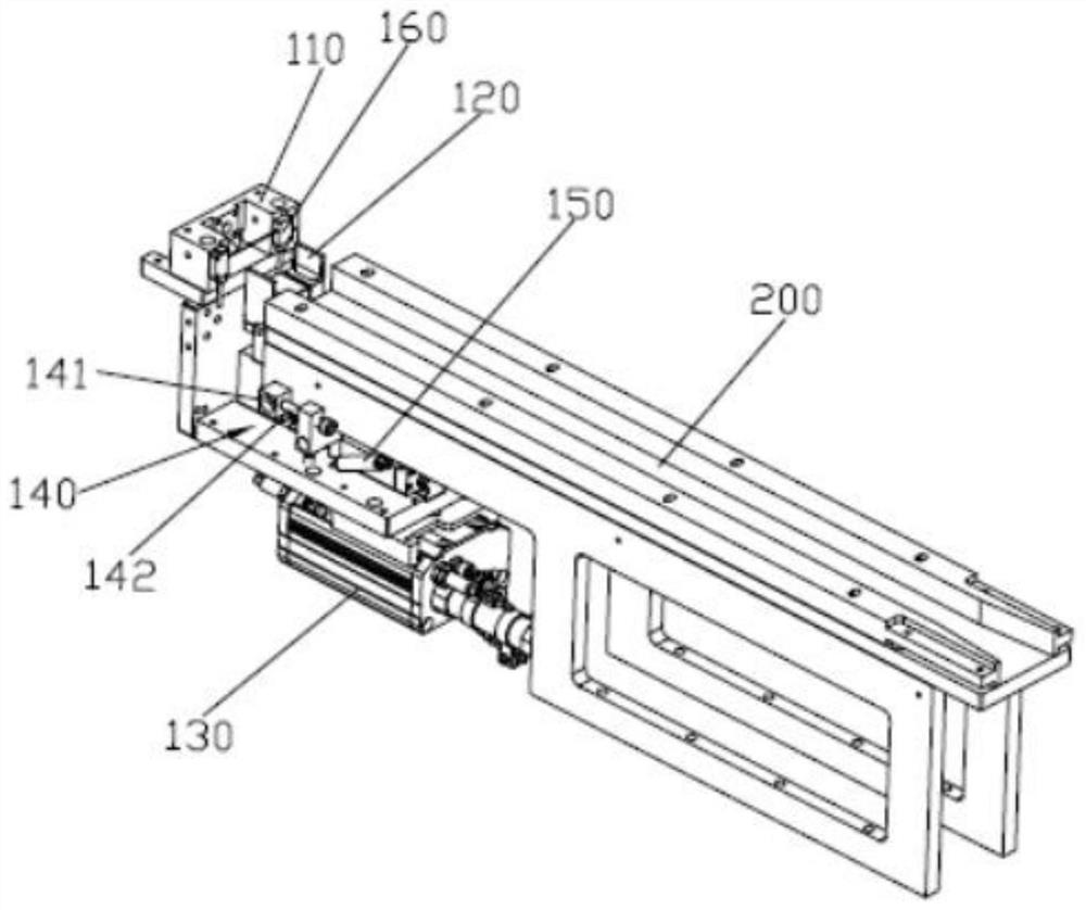
[0018] Such as Figure 1 to Figure 3 As shown, the embodiment of the present invention provides a material separation mechanism 100, the material separation mechanism 100 includes an end material fixing assembly 110 for fixing the first material, an intermediate material fixing assembly 120 for fixing the second material, Drive the end material fixing assembly 110 together with the intermediate material fixing assembly 120 along the extension direction of the feeding tr...


PUM


Abstract

The invention provides a material separation mechanism, and belongs to the technical field of material separation. The material separation mechanism comprises an end material fixing assembly for fixing a first material, a middle material fixing assembly for fixing a second material, a pneumatic sliding table, a separation limiting assembly and an elastic resetting assembly, wherein the pneumatic sliding table drives the end material fixing assembly and the middle material fixing assembly to move together close to or away from the tail end of a feeding rail in the extending direction of the feeding rail; the separation limiting assembly limits the travel of the middle material fixing assembly moving away from the tail end of the feeding rail; and the elastic resetting assembly forces the end material fixing assembly and the middle material fixing assembly to keep original relative positions. The middle material fixing assembly and the end material fixing assembly are sequentially in butt joint with the tail end of the feeding rail, the pneumatic sliding table is in direct driving connection with the end material fixing assembly, and the middle material fixing assembly and the end material fixing assembly are relatively connected slidably. According to the technical scheme, the separation requirements that two materials can be separated at a time and the separation direction is parallel to the feeding direction can be met.

Description

technical field [0001] The invention relates to the technical field of material separation, in particular to a material separation mechanism. Background technique [0002] In the production process of the product, it is often necessary to transfer the material from one process to another. This process is usually completed by a feeding track, and when the material is transported from one process to another process through the feeding track, it needs to be divided. The material mechanism separates the materials one by one, so that another process can pick up the materials one by one to perform corresponding processing operations on them. However, the distributing mechanism currently on the market can generally only dispose one material at a time, and the distributing direction is perpendicular to the incoming material direction. When the incoming material direction is parallel, it cannot meet the powder demand of these processes. Contents of the invention [0003] The main...

Claims


Application Information

Patent Timeline
IPC IPC(8): B65G35/00B65G47/29B65G47/90
CPCB65G35/00B65G47/29B65G47/901B65G2812/99
Inventor 刘勇智周华国廖建勇
Owner 深圳市合利士智能装备有限公司
Learn More