Feeding mechanical hand

A manipulator and material feeding technology, which is applied in the field of manipulators, can solve problems such as broken tiles, insufficient feeding, and waste of tiles.

Inactive Publication Date: 2020-10-27
广州国智机电设备有限公司
View PDF6 Cites 0 Cited by
  • Summary
  • Abstract
  • Description
  • Claims
  • Application Information

AI Technical Summary

Problems solved by technology

[0004] Aiming at an existing feeding manipulator, when sucking tiles, the surface of tiles in the south will be wet due to south wind, making the surface of tiles smooth, causing the sucker to slip during the process of sucking tiles, r

Method used


Image

  • Feeding mechanical hand
  • Feeding mechanical hand
  • Feeding mechanical hand

Examples


Embodiment 1

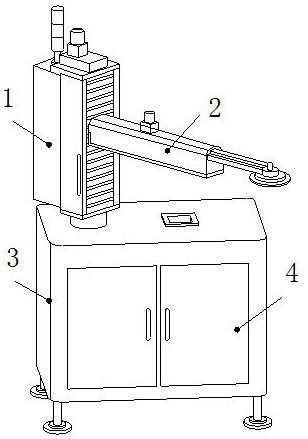
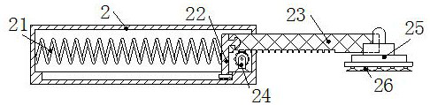
[0029] The invention provides a feeding manipulator, the structure of which includes a rotating column 1, a mechanical arm 2, a base 3, and a locker 4. The bottom of the rotating column 1 is movably engaged with the upper wall of the base 3, and the mechanical arm 2 is mounted One side of the rotating column 1, the front side of the base 3 is provided with a locker 4, and the mechanical arm 2 includes a telescopic spring 21, a positioning block 22, a telescopic rod 23, a runner 24, a grabbing head 25, and a suction block 26, The left end of the telescopic spring 21 is embedded in the left inner wall of the mechanical arm 2, the left side of the positioning block 22 is welded to the right end of the telescopic spring 21, and the bottom of the positioning block 22 is connected to the inner bottom of the mechanical arm 2 through a gap. The telescopic rod 23 The left end is embedded and fixed on the right side of the positioning block 22 and runs through the right wall of the mecha...

Embodiment 2

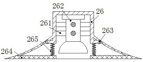
[0035] In the figure, the suction block 26 includes a fixed rod 261, a suction cup 262, a rotary block 263, a cleaning plate 264, and a limit spring 265. One end of the fixed rod 261 is welded to the inner wall of the suction block 26, and the suction cup 262 is embedded in the fixed At the other end of the rod 261, the turning block 263 is connected to the inner wall of the suction block 26 through bolts, the cleaning plate 264 is embedded in the bottom of the suction block 26, and the limiting spring 265 is welded between the limiting spring 265 and the turning block 263 , the bottom of the suction block 26 can rotate around the rotating block 263, and the elasticity of the limit spring 265 makes the cleaning plate 264 have elastic force, which is beneficial to squeeze the cleaning plate 264 to clean the tiles when sucking the tiles, so that the suction cup 262 can suck tile surface.

[0036]In the figure, the cleaning board 264 includes a sponge board b1, a brush b2, and a ...


PUM


Abstract

The invention discloses a feeding mechanical hand. The feeding mechanical hand structurally comprises a rotary column, a mechanical arm, a base and a storage cabinet. The bottom of the rotary column is movably clamped to the upper wall of the base, the mechanical arm is cooperatively mounted on one side of the rotary column, and the storage cabinet is arranged on the front side of the base. The feeding mechanical hand has the beneficial effects that a positioning block drives a telescopic rod to stretch out to the needed length, a suction block is located on the upper surface of a ceramic tile, a through pipe sucks air upwards, a suction plate is pulled upwards, a sucker tightly sucks the surface of the ceramic tile, the adsorption force for the ceramic tile is improved through suction grooves in the bottom of the suction plate, dust and water on the ceramic tile are wiped away through brushes and sponge blocks at the bottoms of cleaning plates, the situation that as water exists on the surface of the ceramic tile, the ceramic tile and the sucker slip, and the ceramic tile falls and is smashed into pieces in the feeding process is avoided, and grabbing of the mechanical hand for the ceramic tile is improved.

Description

technical field [0001] The invention relates to the field of manipulators, in particular to a feeding manipulator. Background technique [0002] The manipulator is a mechanical device that enters a pre-edited program and then automatically operates according to the program steps. The feeding manipulator sucks the surface of the tiles through the suction cup at the bottom of the manipulator to avoid the tiles from falling when transporting tile products. [0003] At present, there is an existing feeding manipulator. When absorbing ceramic tiles, in the south, due to the south wind, the surface of the ceramic tiles will be wet, making the surface of the ceramic tiles smooth, causing the suction cup to slip during the process of absorbing the ceramic tiles, resulting in untimely feeding of the ceramic tiles. Wipe and clean the tiles, otherwise the tiles will easily fall on the ground and break, resulting in waste of tiles. Contents of the invention [0004] Aiming at an exis...

Claims


Application Information

Patent Timeline
IPC IPC(8): B65G47/91
CPCB65G47/91
Inventor 张爱琴
Owner 广州国智机电设备有限公司
Why Eureka
Try Eureka