Conveying and impurity suction device for melt-blown cloth production

A melt-blown cloth and cloth feeding technology, which is applied in the field of melt-blown cloth production equipment, can solve the problems of low suction efficiency of adherent fibers on the surface of melt-blown cloth, difficulty in achieving reciprocating suction and removal, and poor quality.

Active Publication Date: 2020-10-27
桐乡市中瑞环保科技有限公司
View PDF12 Cites 8 Cited by
  • Summary
  • Abstract
  • Description
  • Claims
  • Application Information

AI Technical Summary

Problems solved by technology

During the production process of melt-blown cloth, the high-speed hot air flow is used to draw the polymer melt stream extruded from the spinneret hole of the die head, thereby forming ultra-fine fibers and collecting them on the condensation net curtain or roller, and at the same time Bonded to become a melt-blown nonwoven fabric. The ultra-fine fibers formed by the polymer melt can be collected into a mesh cloth structure by using the web forming equipment. Roll and other processing procedures, during the process of melt-blown cloth being melt-blown into a web and cooled and shaped by using a web-forming equipment, some of the ultra-fine fibers drawn from the polymer melt will be difficult to be effectively collected due to factors such as breakage. A firm network structure is formed, so that the surface of the melt-blown cloth conveyed by the web-forming equipment will be adhered to the fluffy fiber material, so it is necessary to separate the adhered fibers before the melt-blown cloth is slitting and winding. Material removal can ensure the quality of the melt-blown cloth in the subsequent winding process. The existing method for removing the adhered fiber material on the surface of the melt-blown cloth is mainly used in the process of conveying the melt-blown cloth, using the miscellaneous air blown that is arranged in close proximity. The pipe absorbs the fiber material adhered to the surface of the melt-blown cloth, and the miscellaneous air pipe is connected with the external blower. side, the miscellaneous air duct can only absorb the adhesive fibers on the surface of the meltblown cloth once, and it is difficult to use the miscellaneous air duct to continuously and reciprocally absorb the adhesive fibers on the surface of the meltblown cloth, resulting in sticky fibers on the surface of the meltblown cloth. The absorption efficiency of the attached fibers is low and the quality is poor. In order to improve the absorption efficiency of the adhered fibers on the surface of the melt-blown cloth, it is necessary to bring the miscellaneous air duct and the surface of the melt-blown cloth as close as possible, and at the same time increase the air volume of the miscellaneous air duct, but in When the above method is used to absorb fibers, the melt blown cloth during the transmission process will not be compressed and fixed on both sides of the melt blown cloth, and the texture of the melt blown cloth is relatively light, so that the melt blown cloth will be broken due to the suction of the miscellaneous suction duct. Adsorption fits the suction inlet of the suction duct, causing the melt blown cloth to be pulled and twisted under the adsorption of the suction duct, making it difficult to ensure the normal and orderly transmission and processing of the melt blown cloth, and reduce the The quality of the production and processing of meltblown cloth is difficult to meet the needs of production and use

Method used


Image

  • Conveying and impurity suction device for melt-blown cloth production
  • Conveying and impurity suction device for melt-blown cloth production
  • Conveying and impurity suction device for melt-blown cloth production

Examples


Embodiment Construction

[0023] In order to further describe the present invention, a specific implementation of a conveying and gettering device for the production of melt blown cloth will be further described below in conjunction with the accompanying drawings. The following examples are explanations of the present invention and the present invention is not limited to the following examples.

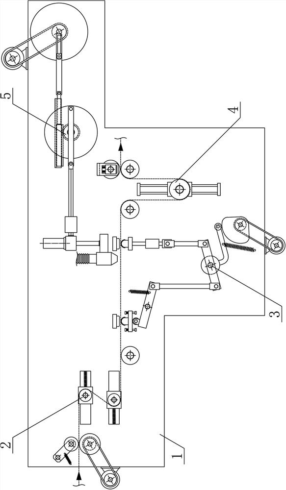
[0024] like figure 1 As shown, the present invention is a transmission and absorption device for melt-blown cloth production, including a spreading processing support 1, a cloth feeding guide mechanism 2, a cloth pressing fixing mechanism 3, a cloth outlet guiding mechanism 4 and a reciprocating suction mechanism 5 , the cloth feeding guide mechanism 2, the cloth pressing fixing mechanism 3 and the cloth outlet guiding mechanism 4 are successively arranged on the spread processing support 1 along the horizontal direction, and the reciprocating suction mechanism 5 is arranged on the spread processing support 1 o...


PUM


Abstract

The invention discloses a conveying and impurity suction device for melt-blown cloth production, and belongs to the field of melt-blown cloth production equipment. A melt-blown cloth pressing rotary roller is arranged on the upper side of a cloth feeding and conveying rotary roller, a front material guide rotating roller and a rear material guide rotating roller are rotationally connected to a cloth conveying machining bracket in sequence, a front positioning cloth pressing plate is fixedly arranged on the upper side of a front lifting guide plate, a rear positioning cloth pressing plate is fixedly arranged on the upper side of a rear lifting guide plate, a cloth discharging and conveying rotary roller is rotationally connected to the cloth conveying machining bracket on one side of the rear material guide rotating roller, a lifting material guide rotating roller is rotationally connected to a lifting reciprocating guide plate, a reciprocating impurity suction material pipe is arrangedbetween the front positioning cloth pressing plate and the rear positioning cloth pressing plate, and an impurity suction connecting hose is arranged in the middle of the upper side of the reciprocating impurity suction material pipe in a communicating mode. The conveying and impurity suction device for melt-blown cloth production is reasonable in structural design, melt-blown cloth can be pressed and fixed intermittently, efficiently and stably in the conveying process, then the melt-blown cloth can be subjected to segmented impurity suction machining conveniently and smoothly, the automation degree of melt-blown cloth production and machining is improved, and the requirements of production and use are met.

Description

technical field [0001] The invention belongs to the field of melt-blown cloth production equipment, and in particular relates to a conveying and absorbing device for melt-blown cloth production, which is mainly used in the continuous production and processing of melt-blown cloth. Background technique [0002] Melt-blown cloth is the core material of the mask. The melt-blown cloth filter material is randomly distributed and bonded together by polypropylene microfibers. The appearance is white, flat and soft. The random distribution of polypropylene microfibers provides more heat between fibers Bonding opportunities, the diameter of polypropylene ultrafine fibers can reach 1-5 microns, and the ultrafine fibers with a unique capillary structure increase the number and surface area of ​​fibers per unit area, with many voids, fluffy structure and good wrinkle resistance, making melt blown cloth The filter material has a larger specific surface area and higher porosity, so that th...

Claims


Application Information

Patent Timeline
Patent Type & Authority Applications(China)
IPC IPC(8): D06G1/00
CPCD06G1/00
Inventor 陈建林
Owner 桐乡市中瑞环保科技有限公司
Why Eureka
Try Eureka