
Electric iron tower main material reinforcing device

A reinforcement device and a technology for power towers, applied in towers, building maintenance, building types, etc., can solve problems such as no seismic buffer effect, affecting construction efficiency, poor environmental adaptability, etc.

Inactive Publication Date: 2020-10-27
李桂珍
View PDF0 Cites 1 Cited by
  • Summary
  • Abstract
  • Description
  • Claims
  • Application Information

AI Technical Summary

Problems solved by technology

[0004] However, the existing reinforcement device for the main material of the power tower has poor reinforcement effect, does not have a good seismic buffer effect, poor environmental adaptability, and the existing device structure is complex, which affects the construction efficiency

Method used


Image

  • Electric iron tower main material reinforcing device
  • Electric iron tower main material reinforcing device
  • Electric iron tower main material reinforcing device

Examples


Embodiment 1

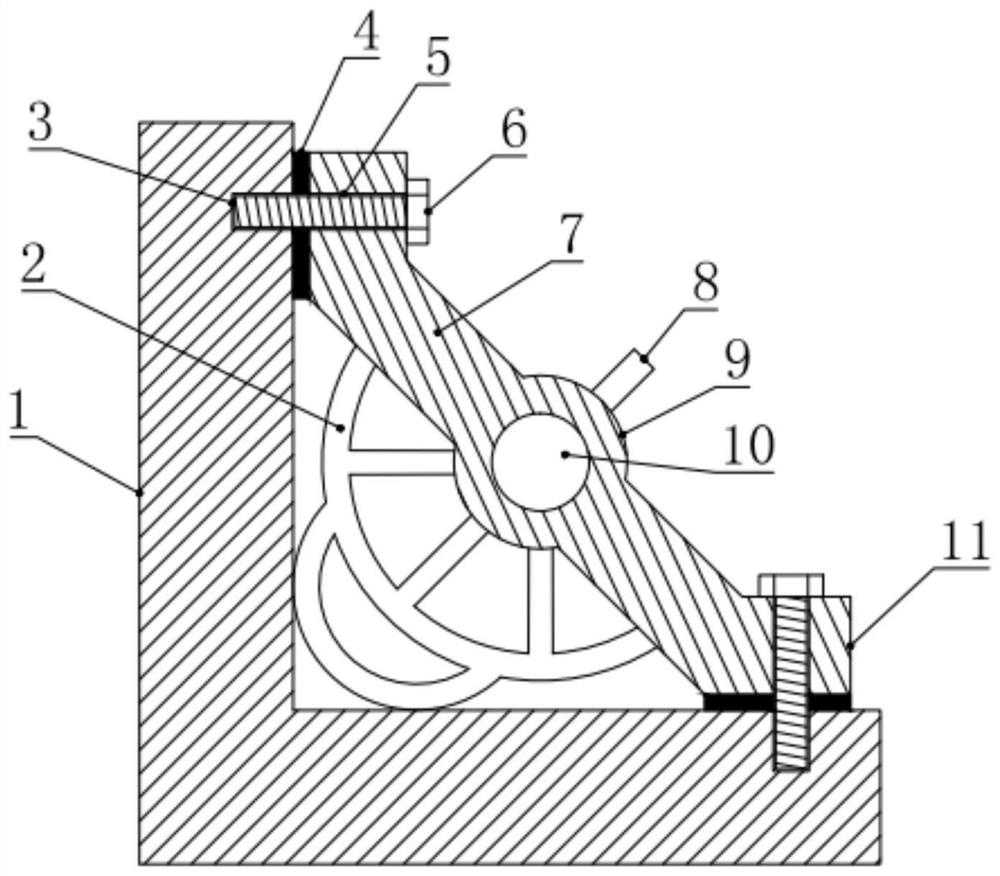
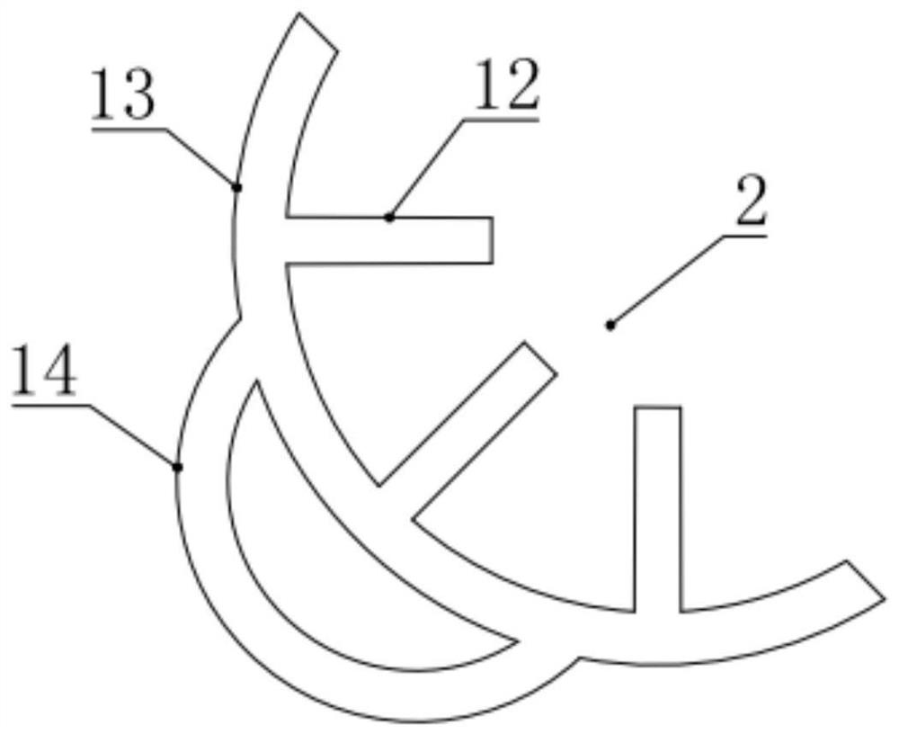
[0025] see figure 1 , in an embodiment of the present invention, a main material reinforcement device for an electric power tower includes a main material plate 1 with an L-shaped structure, and a plurality of reinforcing sloping plates 7 are installed and fixed on the inner side of the main material plate 1, and the reinforcing sloping plates 7 The side close to the main material plate 1 is also fixed with a plurality of elastic support components 2, and the elastic support components 2 elastically abut against the two branches of the main material plate 1, and the two adjacent reinforcement slant plates 7 The turnbuckle bolts 15 are also supported and fixed between them, and the two ends of the turnbuckle bolts 15 are correspondingly connected and fixed with the two reinforced sloping plates 7 .

[0026] In the embodiment of the present invention, by fixing the reinforcement slant plate 7 on the inner side of the main material plate 1, the reinforcement slant plate 7 can for...

Embodiment 2

[0028] see Figure 1-4 , the difference between this embodiment and embodiment 1 is:

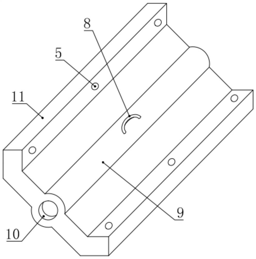
[0029] In this example, if figure 1 and 2 As shown, the reinforcement slant plate 7 is evenly distributed on the inner side of the main material plate 1, the two branches of the reinforcement slant plate 7 and the main material plate 1 are set at an angle of 45°, and the two ends of the reinforcement slant plate 7 are provided with The two branches of the main material plate 1 are parallel extensions 11, a gasket 4 is also provided between the extensions 11 and the main material plate 1, and a plurality of second screw holes 5 are opened on the extensions 11, which are in line with the described The main material plate 1 corresponding to the second screw hole 5 is provided with a first screw hole 3, and the fixing bolt 6 passes through the second screw hole 5 and the gasket 4 and is fixed on the first screw hole 3, which realizes the reinforcement The inclined plate 7 is connected and fix...


PUM


Abstract

The invention relates to the technical field of power supply equipment, in particular to an electric iron tower main material reinforcing device. The electric iron tower main material reinforcing device comprises a main material plate of an L-shaped structure, wherein a plurality of reinforcing inclined plates are mounted and fixed inside the main material plate; sides, close to the main materialplate, of the reinforcing inclined plates are fixedly provided with a plurality of elastic supporting assemblies; the elastic supporting assemblies elastically abuts against two branches of the main material plate; a flower basket bolt is further supported and fixed between adjacent two reinforcing inclined plates; and the two ends of the lower basket bolt are blocked, connected and fixed with thetwo reinforcing inclined plates correspondingly. The electric iron tower main material reinforcing device is good in reinforcing effect, has better anti-seismic buffer effect, is good in environmental suitability, is simple in structure, and improves construction operation efficiency.

Description

technical field [0001] The invention relates to the technical field of power supply equipment, in particular to a reinforcement device for the main material of an electric power tower. Background technique [0002] Power towers generally refer to transmission line towers, which are tower-shaped buildings for power transmission. Their structural characteristics are that all kinds of towers are space truss structures, and the rods are mainly composed of a single equal-sided angle steel or a combined angle steel. Composed of connecting steel plates and bolts, individual parts such as tower feet are welded into an assembly by several steel plates, so hot-dip galvanized anti-corrosion, transportation and construction erection are extremely convenient. [0003] In recent years, due to the significant increase in the demand for electric energy, more insulator strings and sensors need to be added to the iron tower, which increases the load to be borne by the iron tower. The old tr...

Claims


Application Information

Patent Timeline
IPC IPC(8): E04G23/02E04H12/08E04H12/34
CPCE04G23/0218E04H12/08E04H12/34
Inventor 李桂珍
Owner 李桂珍
Learn More