Composite percussion drilling tool

A technology for percussion drilling and tools, which is applied to drilling equipment, driving devices for drilling in wellbore, and earth-moving drilling, etc., can solve the problems of fast stick-slip vibration failure of drill bits, low ROP, and high drilling costs.

Pending Publication Date: 2020-10-27
韦伟
5 Cites 0 Cited by

AI-Extracted Technical Summary

Problems solved by technology

[0003] In the process of drilling deep and hard ground, traditional composite percussion drilling tools often need to replace the drill bit due to problems such as low ROP, rapid failure of t...

Abstract

The invention relates to the field of drilling tools, in particular to a composite percussion drilling tool which comprises a connecting base mechanism, an indicating mechanism, a turbine reversing mechanism and an axial impact mechanism. The indicating mechanism is connected with the connecting base mechanism. The turbine reversing mechanism is connected with the connecting base mechanism. The axial impact mechanism is connected with the turbine reversing mechanism, and comprises an impact hammer, an impact base, a second shell, a lower ratchet wheel, an anti-falling ring, a TC static sleeveand a lower connector. The second shell is connected with the turbine reversing mechanism. The lower section of the second shell is fixedly connected with the lower connector. The lower connector is in interference fit with the TC static sleeve through a spline. The impact base is disposed in the second shell. The impact hammer is disposed in the impact base. The lower ratchet wheel is disposed onthe lower side of the impact base. The anti-falling ring is disposed between the lower ratchet wheel and the lower connector. The composite percussion drilling tool has the advantage of high rock breaking efficiency.

Application Domain

Borehole drives

Technology Topic

RatchetEngineering +6

Image

  • Composite percussion drilling tool
  • Composite percussion drilling tool
  • Composite percussion drilling tool

Examples

  • Experimental program(1)

Example Embodiment

[0018] The present invention will be further described below with reference to the drawings and embodiments.
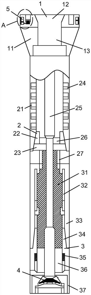
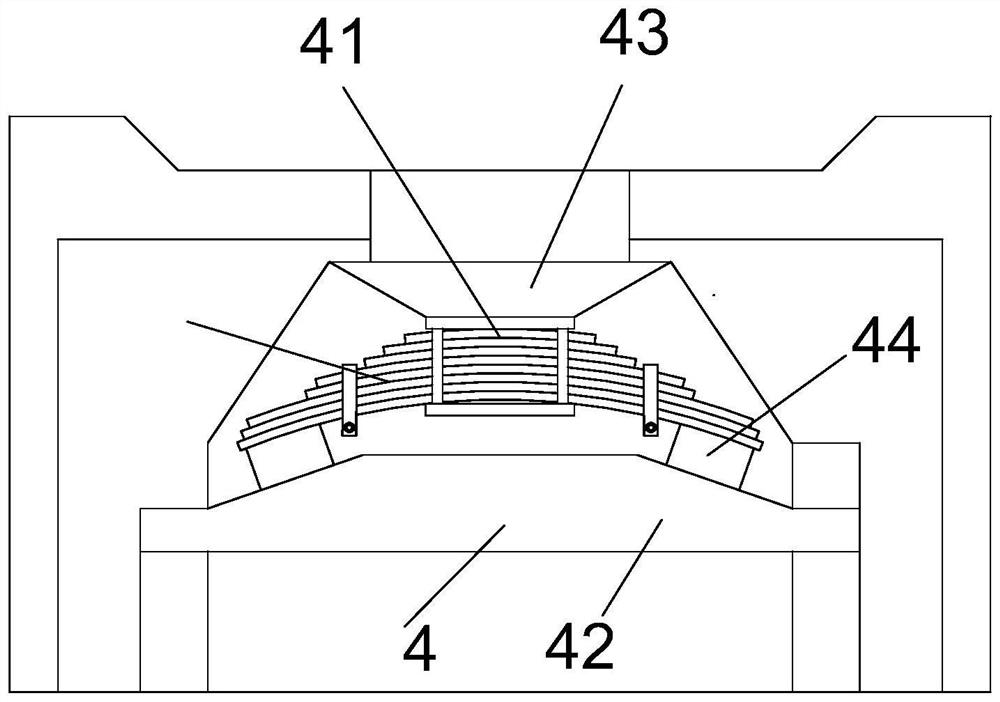
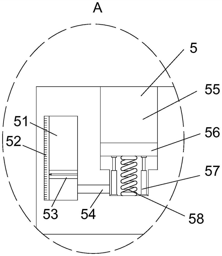
[0019] Please refer to figure 1 , figure 2 with image 3 , A composite percussion drilling tool, comprising a connecting seat mechanism 1, an indicating mechanism 5, a turbine torsion mechanism 2, an axial impact mechanism 3, and a pressure applying mechanism 4. The indicating mechanism 5 is connected to the connecting seat mechanism 1; the turbine torsion The mechanism 2 is connected with the connecting seat mechanism 1; the axial impact mechanism 3 is connected with the turbine torsion mechanism 2; the pressure applying mechanism 4 is connected in the lower connecting head 37. The turbine torsion mechanism 2 includes a first housing 21 and a bearing The sleeve 22, the adjusting ring 23, the turbine 24, the turbine shaft 25, the bearing 26 and the longitudinal impact block 27. The longitudinal impact block 27 is installed at the lower end of the first housing 21, and the longitudinal impact block 27 is fixed to the second housing 33 The first housing 21 is fixedly connected with a bearing sleeve 22, an adjusting ring 23 is installed under the bearing sleeve 22, and a bearing 26 is installed in the bearing sleeve 22; the central position in the first housing 21 is set There is a turbine shaft 25. The turbine shaft 25 is rotatably connected in the first housing 21 through a bearing 26, and the outer surface of the turbine shaft 25 is splined with a plurality of uniformly distributed turbines 24. When in use, the drilling fluid drives the medium to drive The turbine 24 and the turbine shaft 25 rotate, so that the rotation of the turbine 24 and the turbine shaft 25 is converted into a high-frequency longitudinal impact, which causes the drill bit to generate torsional vibration.
[0020] reference figure 1 As shown, the axial impact mechanism 3 includes an impact hammer 31, an impact seat 32, a second housing 33, a lower ratchet 34, an anti-drop ring 35, a TC static sleeve 36, and a lower connector 37. The second housing 33 is connected to the turbine torsion mechanism 2, and the lower section of the second housing 33 is fixedly connected with a lower connector 37, and a TC static sleeve 36 is installed on the lower connector 37 through spline interference fit; the second housing 33 is installed in There is an impact seat 32, an impact hammer 31 is installed in the impact seat 32, and a lower ratchet wheel 34 is installed under the impact seat 32. An anti-dropping ring 35 is installed between the lower ratchet wheel 34 and the lower connector 37, which is produced by the operation of the impact hammer 31 The axial pulse causes the drill bit to generate axial vibration. Because the drill bit can also generate torsional vibration, the PDC drill bit can achieve torsional cutting function. The torque of the entire drill string remains stable and balanced, which improves the drill bit’s rock breaking efficiency and prevents ring drop 35 Will follow the lower ratchet wheel 34 and the rotary power joint to fall relative to the drill tool assembly. When the anti-drop ring falls to the lower connector 37, the upper end surface will be stuck here and the drill tool assembly will be lifted up, no longer It can prevent the lower ratchet wheel 34 and the rotary power joint from falling off, and improve the reliability of the device, and the TC static sleeve 36 has a centralizing effect on the lower ratchet shaft.
[0021] reference figure 1 As shown, the lower ratchet wheel 34 is provided with an anti-wear belt inlaid with cemented carbide.
[0022] reference figure 1 with figure 2 As shown, the pressing mechanism 4 includes a plate spring 41, a connecting plate 42, a first boss 43 and a second boss 44. The inner wall of the upper end of the lower connector 37 is fixedly connected with the first boss 43, and the lower The connecting head 37 is slidably connected with a connecting plate 42 for connecting the drill bit base. The surface of the connecting plate 42 opposite to the first boss 43 is fixedly connected with two symmetrically arranged second bosses 44, and the first boss 43 passes through a leaf spring. 41 is connected to the two second bosses 44. When the drill bit seat is installed in the lower connector 37, the plate spring 41 is compressed, and under the action of the elastic restoring force of the plate spring 41, the drill bit maintains the drilling pressure. It is expressed as holding the drill bit at the bottom of the well, keeping the bit teeth in close contact with the formation, reducing the transmission loss of impact energy between the bit teeth and the formation rock, and further improving the rock breaking efficiency of the bit.
[0023] reference figure 1 As shown, the connecting seat mechanism 1 includes a connecting seat 11, a chamfer 12, and a mounting hole 13. The lower surface of the connecting seat 11 is fixedly connected to the first housing 21, and the upper surface of the connecting seat 11 is provided with a mounting hole. 13. The opening of the mounting hole 13 is provided with a chamfer 12, and the upper drilling tool is connected to the connecting seat 11, and the upper drilling tool can better enter the mounting hole 13 through the chamfer 12.
[0024] reference figure 1 with image 3 As shown, the indicating mechanism 5 includes a groove 51, a scale bar 52, a first piston 53, a connecting tube 54, a positioning hole 55, a second piston 56, a telescopic rod 57 and a spring 58, and the upper surface of the connecting seat 11 A positioning hole 55 and a groove 51 are provided, and the groove 51 communicates with the positioning hole 55 through a connecting tube 54; the side of the connecting seat 11 is provided with a mounting groove communicating with the groove 51, and the mounting groove is sealed and fixedly connected with Transparent baffle; the groove 51 is slidably connected with a matching first piston 53, the first piston 53 is fixedly connected with an indicating arrow, and the groove 51 is fixedly connected with a scale bar 52; the positioning hole 55 A matching second piston 56 is slidably connected. The lower surface of the second piston 56 is connected to the inner bottom wall of the positioning hole 55 through a spring 58 and a telescopic rod 57. When the upper drilling tool is connected to the connecting seat 11, the upper drilling tool The positioning pin is inserted into the positioning hole 55. At this time, the second piston 56 moves downwards, the spring 58 is compressed, and the gas in the positioning hole 55 enters the groove 51 through the connecting tube 54 so that the first piston 53 moves upward, and the operator By observing the position indicated by the indicating arrow on the first piston 53 on the scale bar 52, it is judged whether the upper drilling tool and the connecting seat 11 are successfully installed, and the burden on the operator is reduced.
[0025] The working principle of the composite percussive drilling tool provided by the present invention is as follows: When the device is in use, the drilling fluid drives the turbine 24 and the turbine shaft 25 to rotate, so that the rotation of the turbine 24 and the turbine shaft 25 is converted into high-frequency longitudinal impact, so that the drill bit performs The torsional vibration is generated, and the axial pulse is generated through the work of the impact hammer 31, which causes the drill bit to generate axial vibration. Because the drill bit can also generate torsional vibration, the torsional cutting function of the PDC drill bit is realized, and the torque of the entire drill string remains stable and balanced. Improve the rock breaking efficiency of the bit; when the device is in use, the bit seat is installed in the lower connector 37. At this time, under the action of the elastic restoring force of the plate spring 41, the bit maintains the bit pressure, and the bit It is held at the bottom of the well to keep the bit teeth in close contact with the formation, reduce the impact energy transmission loss between the bit teeth and the formation rock, and further improve the rock breaking efficiency of the bit.
[0026] The basic principles, main features and advantages of the present invention have been shown and described above. Those skilled in the industry should understand that the present invention is not limited by the foregoing embodiments. The foregoing embodiments and descriptions in the specification only illustrate the principles of the present invention. Without departing from the spirit and scope of the present invention, the present invention will also There are various changes and improvements, and these changes and improvements fall within the scope of the present invention. The scope of protection claimed by the present invention is defined by the appended claims and their equivalents.

PUM

no PUM

Description & Claims & Application Information

We can also present the details of the Description, Claims and Application information to help users get a comprehensive understanding of the technical details of the patent, such as background art, summary of invention, brief description of drawings, description of embodiments, and other original content. On the other hand, users can also determine the specific scope of protection of the technology through the list of claims; as well as understand the changes in the life cycle of the technology with the presentation of the patent timeline. Login to view more.
Why Eureka
Try Eureka