An adjustable differential pressure flowmeter

An adjustable technology for differential pressure flowmeters, applied in the field of differential pressure flowmeters, can solve the problems of placing them at the bottom, reducing the efficiency and convenience of use, and not being able to use vertical pipelines, so as to ensure the measurement accuracy and improve the applicability Effect

Active Publication Date: 2022-01-21
江苏华海测控技术有限公司
View PDF0 Cites 0 Cited by
  • Summary
  • Abstract
  • Description
  • Claims
  • Application Information

AI Technical Summary

Problems solved by technology

Orifice plate flowmeter is a kind of differential pressure flowmeter. It is one of the characteristics of orifice plate flowmeter to use orifice plate as throttling device. The shape of orifice plate includes: standard orifice plate, round orifice plate, eccentric orifice plate and The built-in orifice plate, eccentric orifice plate and circular orifice plate are only suitable for installation on horizontal or inclined pipelines, and cannot be used on vertical pipelines. The disadvantage is that when the measured fluid contains solid particles, the opening or gap It needs to be placed at the bottom. When the gas is precipitated in the measured fluid, the opening or notch needs to be placed at the top. At present, the orifice flowmeter cannot be adjusted according to the actual situation of the fluid during use, resulting in poor applicability of the orifice flowmeter. , the fluid needs to be analyzed in advance before it can be used, and the internal orifice plate is manually adjusted according to the fluid state, which greatly reduces the efficiency and convenience of use, and has a certain impact on production activities

Method used


Image

  • An adjustable differential pressure flowmeter
  • An adjustable differential pressure flowmeter
  • An adjustable differential pressure flowmeter

Examples


Embodiment Construction

[0023] The following will clearly and completely describe the technical solutions in the embodiments of the present invention with reference to the accompanying drawings in the embodiments of the present invention. Obviously, the described embodiments are only some, not all, embodiments of the present invention.

[0024] Examples of the described embodiments are shown in the drawings, wherein like or similar reference numerals designate like or similar elements or elements having the same or similar functions throughout. The embodiments described below by referring to the figures are exemplary and are intended to explain the present invention and should not be construed as limiting the present invention.

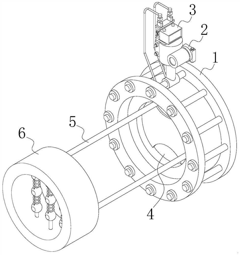
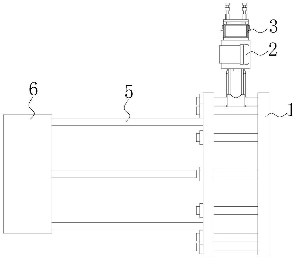
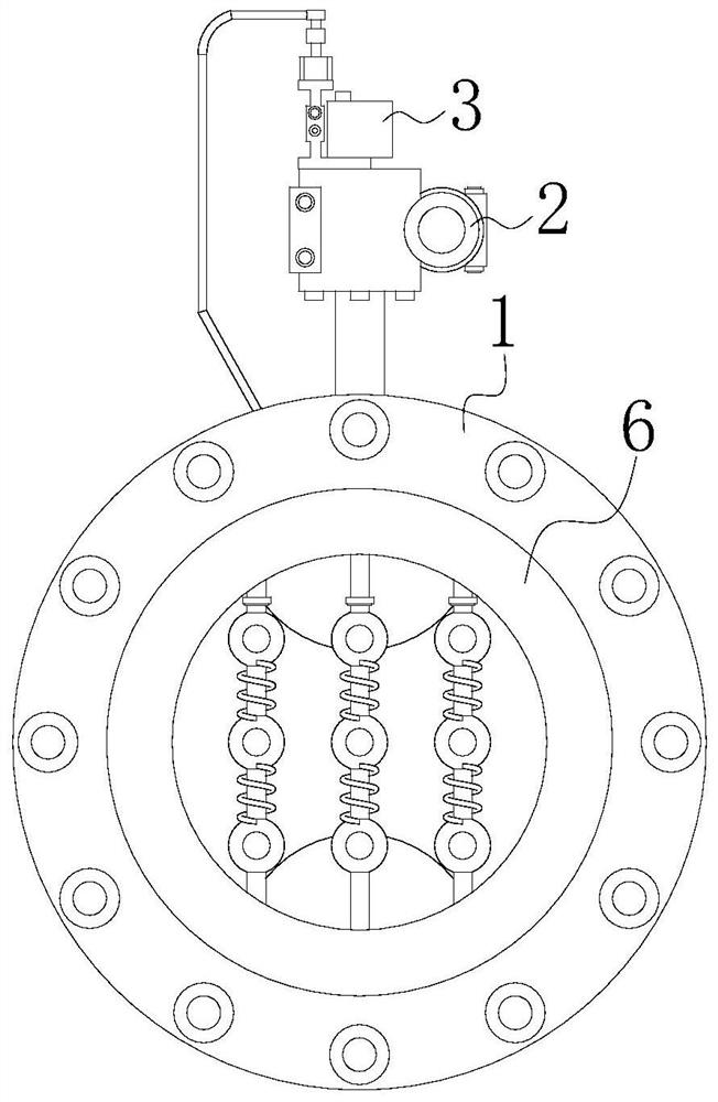
[0025] see Figure 1-8 , the present invention provides a technical solution: an adjustable differential pressure flowmeter, including a fixed plate 1, a differential pressure transmitter 2 and a flow indicator 3 are fixedly installed on the top of the fixed plate 1, and the...


PUM


Abstract

The invention discloses an adjustable differential pressure flowmeter and relates to the technical field of differential pressure flowmeters. The adjustable differential pressure flowmeter includes a fixed plate, a differential pressure transmitter and a flow indicator are fixedly installed on the top of the fixed plate, and a self-adjusting orifice mechanism is fixedly installed in the fixed plate, and the left side of the fixed plate Four connecting rods are equidistantly fixedly connected, and the ends of the four connecting rods away from the fixed plate are all fixedly connected to the two-phase detection mechanism. The two-phase detection mechanism includes a fixed ring piece, an electric heating ring, a vertical rod, a first contact type sensor. The adjustable differential pressure flowmeter cooperates with the self-adjusting orifice mechanism through the two-phase detection mechanism. Compared with the traditional flowmeter, it not only saves the analysis steps of the measured fluid composition, but also can be used without affecting the normal flow of the fluid. In some cases, the detection function is realized based on the flowmeter itself, and the orifice plate is adjusted accordingly according to the detection results.

Description

technical field [0001] The invention relates to the technical field of differential pressure flowmeters, in particular to an adjustable differential pressure flowmeter. Background technique [0002] The differential pressure flowmeter is based on the throttling principle when the fluid flows, and realizes the flow measurement by using the pressure difference generated when the fluid flows through the throttling device. It is one of the more mature and commonly used devices in the field of flowmeters. It is usually composed of a throttling device that can convert the flow of the measured object into a pressure difference signal and a differential pressure flowmeter that can convert the pressure difference into a corresponding flow value and display it. Orifice plate flowmeter is a kind of differential pressure flowmeter. It is one of the characteristics of orifice plate flowmeter to use orifice plate as throttling device. The shape of orifice plate includes: standard orifice...

Claims


Application Information

Patent Timeline
Patent Type & Authority Patents(China)
IPC IPC(8): G01F1/36G01F15/10G01F15/12
CPCG01F1/363G01F15/10G01F15/12
Inventor 徐锋潘娟
Owner 江苏华海测控技术有限公司
Why Eureka
Try Eureka