Optical cable with special-shaped filling ropes

A technology for filling ropes and optical cables, which can be applied to cables, optics, light guides, etc., and can solve the problems of increasing the weight of optical cables, inconvenient construction, and heavy optical cables.

Pending Publication Date: 2020-10-27
CHANGSHU GAOTONG INTELLECT EQUIP CO LTD
View PDF1 Cites 5 Cited by
  • Summary
  • Abstract
  • Description
  • Claims
  • Application Information

AI Technical Summary

Problems solved by technology

[0004] There are following shortcomings in the above-mentioned prior art: 1. The weight of the optical cable is large, and materials such as steel wire armor and annular ribs are arranged inside the optical cable, which increases the weight of the optical cable and brings inconvenience to the construction; 2. The rubber cushion is distributed in adjacent Between loose tubes, adjacent filling ropes, and between loose tubes and filling ropes, it cannot provide compression and earthquake protection between loose tubes and central reinforcements, loose tubes and outer sheaths

Method used


Image

  • Optical cable with special-shaped filling ropes
  • Optical cable with special-shaped filling ropes
  • Optical cable with special-shaped filling ropes

Examples


Embodiment 1

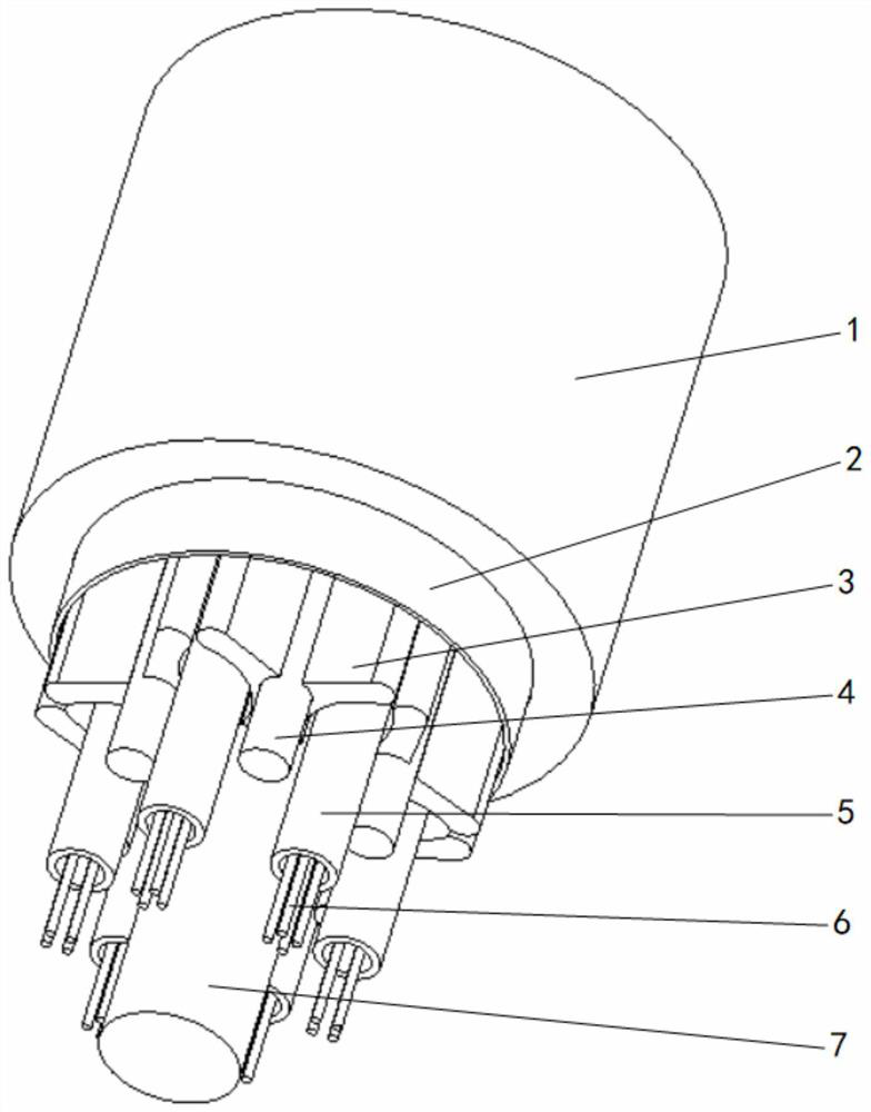
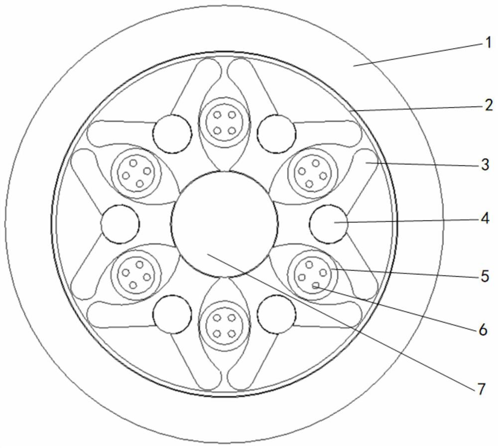
[0031] please see figure 1 , figure 2 and Figure 5 , an optical cable with a special-shaped filling rope, which has an outer sheath 1, a tape layer 2, a central strength member 7 and at least three loose tubes 5, each loose tube is provided with at least one optical fiber 6, and the loose tube 5 Located outside the central reinforcement 7, the tape layer 2 is located outside the loose tube 5, and the outer sheath 1 is extruded outside the tape layer 2, and it is characterized in that there is also a set between the two adjacent loose tubes 5 A filling rope 3, the filling rope 3 is composed of a base 34 and two bifurcated support plates 31 at the top of the base 34, a cavity 33 is formed between the two support plates 31 in the base 34, the cavity 33 top forms an embedding opening 32, the bottom of the base 34 is arc-shaped, and is bonded to the surface of the central reinforcement 7, clockwise, the base 34 of the previous filling rope 3 and the support plate 31 on the left...

Embodiment 2

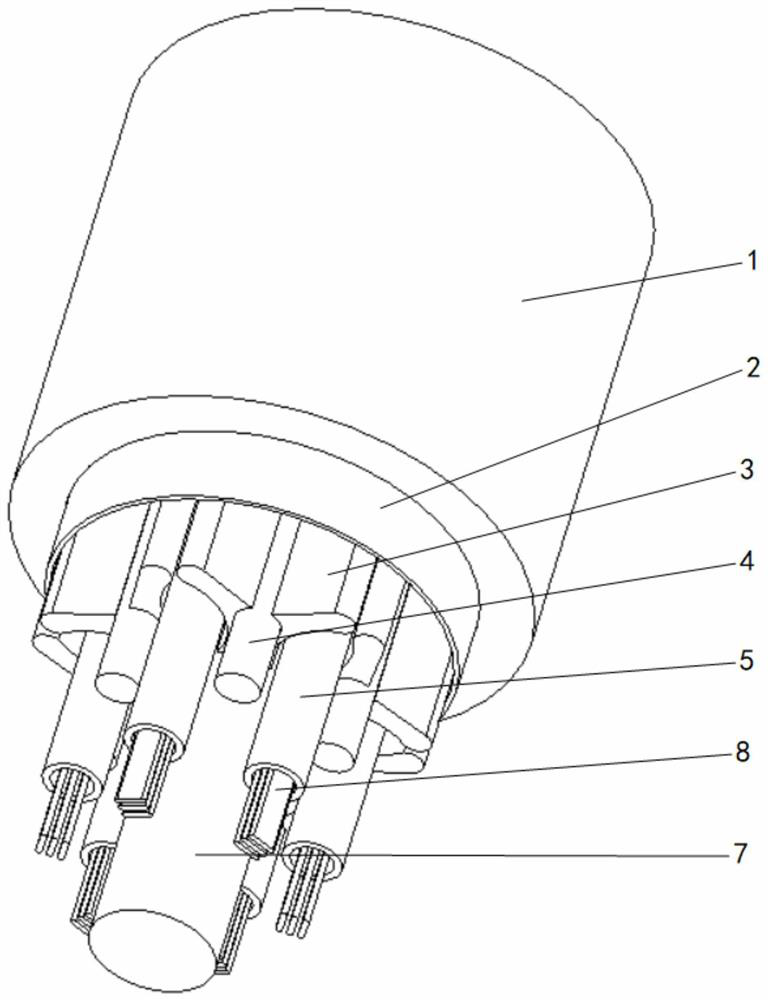
[0033] please see image 3 , Figure 4 and Figure 5 , an optical cable with a special-shaped filling rope, which has an outer sheath 1, a tape layer 2, a central strength member 7 and at least three loose tubes 5, each loose tube is provided with at least one optical fiber ribbon 8, and the loose tube 5 is located outside the central reinforcement 7, the wrapping layer 2 is located outside the loose tube 5, and the outer sheath 1 is extruded outside the wrapping layer 2, which is characterized in that two adjacent loose tubes 5 are also provided with There is a filling rope 3, and the filling rope 3 is composed of a base 34 and two bifurcated support plates 31 located at the top of the base 34, and a cavity 33 is formed between the two support plates 31 to the base 34 to accommodate An embedding opening 32 is formed at the top of the cavity 33, and the bottom of the base 34 is arc-shaped, and is attached to the surface of the central reinforcing member 7. In a clockwise dir...

Embodiment 3

[0035] please see Figure 6 , Figure 7 , Figure 8 and Figure 9, an optical cable with a special-shaped filling rope, which has an outer sheath 1, a tape layer 2, a central strength member 7 and at least three loose tubes 5, each loose tube is provided with at least one optical fiber 6, and the loose tube 5 Located outside the central reinforcement 7, the tape layer 2 is located outside the loose tube 5, and the outer sheath 1 is extruded outside the tape layer 2, and it is characterized in that there is also a set between the two adjacent loose tubes 5 A filling rope 3, the filling rope 3 is composed of a base 34 and two bifurcated support plates 31 at the top of the base 34, a cavity 33 is formed between the two support plates 31 in the base 34, the cavity 33 top forms an embedding opening 32, the bottom of the base 34 is arc-shaped, and is attached to the surface of the central reinforcement 7, and the bottom of the base 34 also forms a limiting groove 35, and the cent...


PUM


Abstract

The invention belongs to the field of cables and particularly relates to a special-shaped filling rope. The cable is provided with an outer protective layer, a belting layer, a central reinforcing member and at least three loose tubes, wherein at least one optical communication component is arranged in each loose tube, the cable is characterized in that a filling rope is further arranged between every two adjacent loose tubes, the filling rope is composed of a base and two branched supporting plates located at the top of the base, an accommodating cavity is formed between the two support plates towards the inside of the base, an embedding opening is formed in the top of the accommodating cavity, the bottom of the base is arc-shaped and is attached to the surface of the central reinforcingpiece, the base of the previous filling rope, the supporting plate on the left side and the base of the next filling rope are close to each other in the clockwise direction to form an oval loose tubecontaining cavity, the loose tube is located in the loose tube containing cavity, and an electric unit is arranged in the containing cavity. The cable has advantages of being simple in structure, goodin heat dissipation performance, resistant to side pressure, shock and torsion, easy to construct and the like.

Description

technical field [0001] The invention belongs to the field of cables, in particular to an optical cable with special-shaped filling ropes. Background technique [0002] With the large-scale promotion of domestic 5G construction, the demand for optical cables is increasing. In some complex environments, optical cables require strong compression performance. [0003] In the prior art, as CN207249204U discloses a kind of explosion-proof optical cable for mining, it is characterized in that: comprise outer sheath, steel wire armoring is installed in described outer sheath, described outer sheath and steel wire armor cross section They are all circular and tightly connected. A central reinforcement is installed inside the steel wire armor, and several loose tubes are installed between the outer surface of the central reinforcement and the inner surface of the steel wire armor. A number of loose tubes and a number of filling ropes are installed between the outer surface of the cen...

Claims


Application Information

Patent Timeline
Patent Type & Authority Applications(China)
IPC IPC(8): G02B6/44H01B7/42
CPCG02B6/443G02B6/4432G02B6/4439H01B7/421
Inventor 戴丽芬
Owner CHANGSHU GAOTONG INTELLECT EQUIP CO LTD
Why Eureka
Try Eureka