
Eureka
For R&D, Eureka makes reading and utilizing patents & technical documents easy.
Eureka AIR
Designed for self-driven R&D workflows. Generate viable solutions, solve complex R&D challenges, empower your innovation with AI.

Eureka Materials
Designed for material experts only. Revolutionize your material R&D, from search, analyze, to developing new materials.

TechResearch
Generate reliable direction feasibility study reports for your R&D in just a few steps.

TechSeek
Discover and master advanced knowledge NOW. Basics, ideas, possibilities, all at once.

TechMind
As an expert in R&D Theories, TechMind can generates customized viable solutions instantly.

TechRisk
Analyze your overall solution with one click, know your potential R&D risks in advance.

TechMonitor
Get weekly tech updates, stay abreast of the latest tech innovations and key insights.
fan assembly
A fan assembly, air quality technology, applied in the direction of space heating and ventilation, space heating and ventilation control input, heating method, etc.
- Summary
- Abstract
- Description
- Claims
- Application Information
AI Technical Summary
Problems solved by technology
Method used
Image

Examples
Embodiment Construction
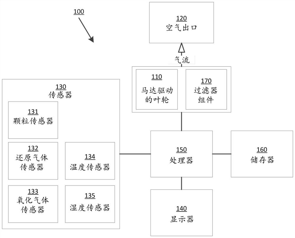
[0044] A fan assembly will now be described that automatically adjusts the speed of the motor driven impeller according to the current air quality. As used herein, the term "fan assembly" refers to a fan assembly configured to generate and deliver airflow for thermal comfort and / or environmental or climate control purposes, and particularly, but not exclusively, for use in a room , household fans that create air circulation and airflow in an office or other home environment. Such fan assemblies may be capable of generating one or more of dehumidified airflow, humidified airflow, purified airflow, filtered airflow, cooling airflow, and heated airflow.
[0045] figure 1 An embodiment of a fan assembly suitable for implementing the methods described herein is schematically shown. The fan assembly 100 is implemented as a combination of mechanical components, computer hardware and software, and includes a motor-driven impeller 110 arranged to generate an airflow, an air outlet 12...
PUM
 Abstract
Description
Claims
Application Information
 - R&D Engineer
- R&D Manager
- IP Professional
- Industry Leading Data Capabilities
- Powerful AI technology
- Patent DNA Extraction
Browse by: Latest US Patents, China's latest patents, Technical Efficacy Thesaurus, Application Domain, Technology Topic, Popular Technical Reports.
© 2024 PatSnap. All rights reserved.Legal|Privacy policy|Modern Slavery Act Transparency Statement|Sitemap|About US| Contact US: help@patsnap.com