
Forecasting lamp

A lampshade and lamp bowl technology, applied in the field of forecasting lamps, can solve the problems of flat lamp cover bursting, affecting the light transmission effect, and lamp cover temperature rise, so as to reduce the difficulty of manual operation, achieve good results, and avoid circuit breakage. Effect

Inactive Publication Date: 2020-10-30
ZHEJIANG TUOPUYUN AGRI SCI & TECH CO LTD
View PDF14 Cites 2 Cited by
  • Summary
  • Abstract
  • Description
  • Claims
  • Application Information

AI Technical Summary

Problems solved by technology

[0003] The existing forecasting lamp attracts insects to fly downwards. During the high-speed flight, the insects will hit the glass plate of the forecasting lamp, and then the insects will fall into the collection bucket, so as to realize the collection and processing of insects; the existing forecasting lamp The lights are all placed outdoors. In rainy days, a large amount of rainwater will fall into the collection bucket, causing the electrical appliances in the forecasting lights to be soaked by rainwater and damage the forecasting lights; and the existing forecasting lights can realize the attraction flying insects, and collect flying insects, but the lamp cover used in this document has a planar structure, and this planar structure causes flying insects to pile up on the lamp cover to block the light after they hit the glass plate At the same time, rain, snow and dust will also fall into the stack on the cover, so it is necessary to clean the lampshade every day, otherwise it will affect the light transmission effect, which will cause poor insect trapping effect; and because the insects, dust, rain and snow, etc. cover, it will also cause the temperature of the lamp cover to rise continuously, and the lamp cover with a flat structure will burst due to high temperature, and then a fire will occur

Method used


Image

  • Forecasting lamp
  • Forecasting lamp
  • Forecasting lamp

Examples


Embodiment Construction

[0030] In order to enable those skilled in the art to better understand the solutions of the present invention, the technical solutions in the embodiments of the present invention will be clearly and completely described below in conjunction with the drawings in the embodiments of the present invention.

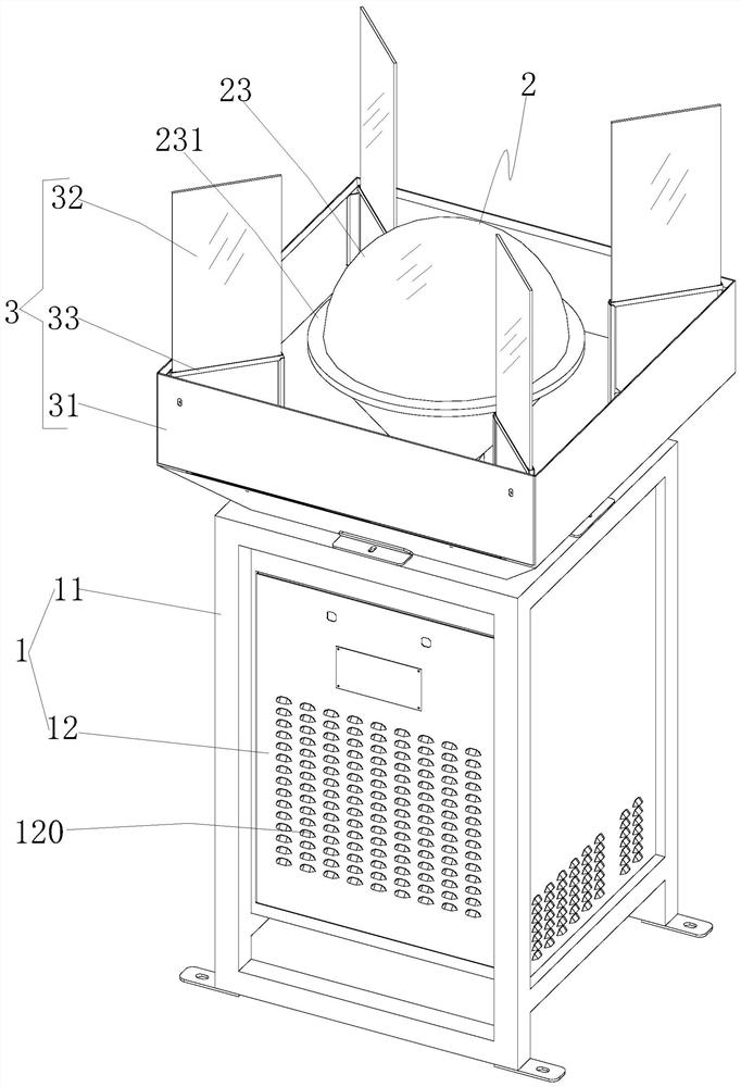
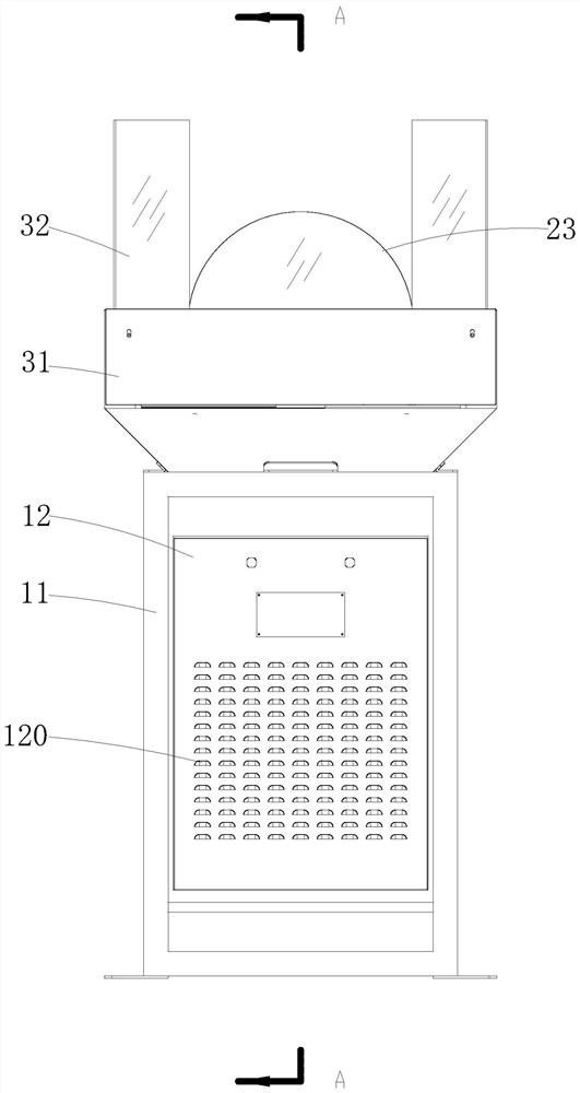
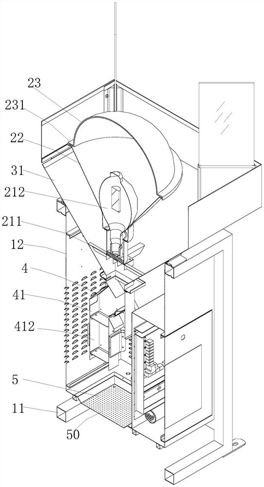
[0031] Such as Figure 1-13As shown, a kind of forecasting lamp comprises box body 1, insect introduction device 2, insect catcher device 3, channel device 4 and collection device 5, wherein said box body 1 is a metal box, and this box body 1 is made of metal box frame 11 and box plate 12 of metal material, on the box plate 12, there are a plurality of heat dissipation through holes 120; The collection devices 5 are all arranged in the middle of the box body 1; wherein the insect-inducing device 2 is used to attract flying insects to fly downward in a spiral manner, and the insect-introducing device 2 includes a light source part 21, a lamp bowl 22 and a lampshade 23, and the...


PUM


Abstract

The invention discloses a forecasting lamp. The forecasting lamp comprises a box body, an insect attracting device used for emitting light to attract winged insects, an insect receiving device used for collecting the winged insects, a channel device used for allowing the winged insects to pass through and draining water, and a collecting device arranged on the box body. The channel device comprises a channel piece provided with a first channel and a second channel, a blocking piece used for closing the first channel or / and the second channel and a driving part, and the driving part drives theblocking piece to act. The surface of a lamp cover is ensured to be clean, insect body stacking prevention and free insect body cleaning are achieved, no accumulated water exists in rainy days, manualdaily cleaning and maintenance are not needed, and light transmission is not affected after long-time use; the insect trapping efficiency is not influenced; and the channel device can be switched tocollect winged insects or drain water according to weather, the overall structure is simple, the cost of the whole forecasting lamp is low, the winged insects cannot be accumulated to block a drain pipe, the drainage effect is good, and the drainage stability is high.

Description

technical field [0001] The invention belongs to the technical field of disease and insect pest forecasting, and in particular relates to a forecasting lamp. Background technique [0002] The food of insects is usually vegetation, so plants are eaten by insects in large quantities, causing vegetation damage, because in order to solve the damage caused by insects to vegetation, using the phototaxis of insects to lure pests through light sources is one of the mainstream methods of forecasting lights. [0003] The existing forecasting lamp attracts insects to fly downwards. During the high-speed flight, the insects will hit the glass plate of the forecasting lamp, and then the insects will fall into the collection bucket, so as to realize the collection and processing of insects; the existing forecasting lamp The lights are all placed outdoors. In rainy days, a large amount of rainwater will fall into the collection bucket, causing the electrical appliances in the forecasting li...

Claims


Application Information

Patent Timeline
Patent Type & Authority Applications(China)
IPC IPC(8): A01M1/04A01M1/20F21S8/00F21V15/01F21V31/00F21V17/10
CPCA01M1/04A01M1/2094F21S8/00F21V3/02F21V15/01F21V17/10F21V31/00
Inventor 朱旭华陈渝阳李彬周涛
Owner ZHEJIANG TUOPUYUN AGRI SCI & TECH CO LTD
Learn More