Workbench for iron ring spot welding

A workbench and spot welding technology, applied in welding equipment, manufacturing tools, metal processing equipment, etc., can solve problems such as eye deformation, glasses that easily compress the bridge of the nose, and adverse eye blood circulation

Active Publication Date: 2020-10-30
陈泉有
View PDF6 Cites 0 Cited by
  • Summary
  • Abstract
  • Description
  • Claims
  • Application Information

AI Technical Summary

Problems solved by technology

[0002] At present, the workers generally carry out spot welding on the hoop on the workbench. The workbench used for spot welding is generally a simple structure with legs and a table top, which only has the function of placing the hoop. When the worker spot welds the hoop There will be flashes, and the flashes will make the eyes feel very uncomfortable. In order to protect the eyes, workers usually wear glasses, but wearing glasses for a long time is not conducive to the blood circulation of the eyes, and it is easy to cause deformation of the eyes, and the glasses are easy to oppress the bridge of the nose. Depression on both sides of the nose

Method used


Image

  • Workbench for iron ring spot welding
  • Workbench for iron ring spot welding
  • Workbench for iron ring spot welding

Examples


Embodiment 1

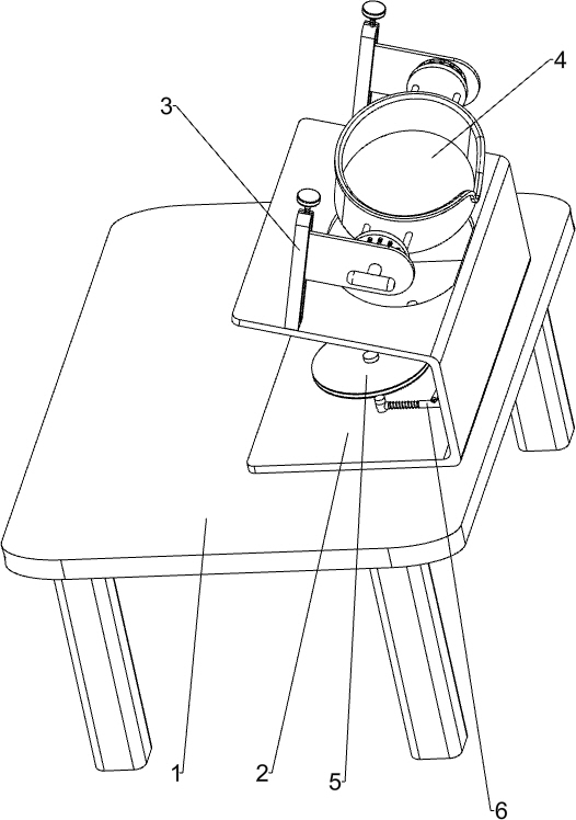
[0023] A workbench for iron ring spot welding, such as Figure 1-4 As shown, it includes a stand 1, a mounting plate 2, a height adjustment device 3, an angle adjustment device 4 and a positioning disc 5. The top right side of the stand 1 is connected with a mounting plate 2, and the top of the mounting plate 2 is equipped with a height adjustment In the device 3, an angle adjustment device 4 is installed on the height adjustment device 3, and a positioning disc 5 is connected to the inner top of the mounting plate 2.

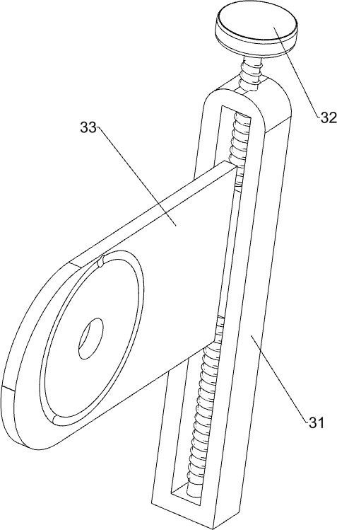
[0024] The height adjustment device 3 includes a slide rail 31, a screw rod 32 and a slide plate 33, the front and rear sides of the mounting plate 2 top are connected with a slide rail 31, the slide rail 31 is slidably connected with a slide block, and the top of the slide rail 31 rotates Type is connected with screw rod 32, and the bottom end of screw rod 32 passes slide block, and screw rod 32 is connected with slide block by the mode of screw connection, an...

Embodiment 2

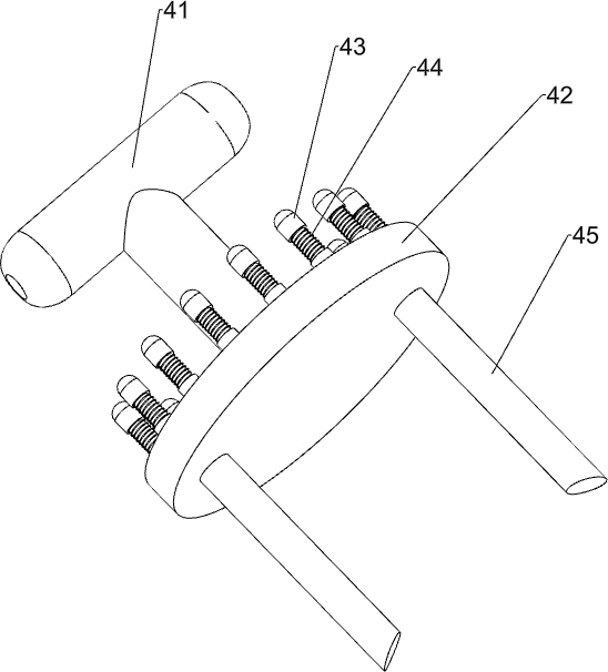
[0028] On the basis of Example 1, such as figure 1 and Figure 5 As shown, a fixing device 6 is also included, and the fixing device 6 includes a second rotating handle 61, a second rotating disk 62, a connecting plate 63, a clamp block 64, a second spring 65 and a second telescopic rod 66, and the positioning disk 5 right The inner top of the mounting plate 2 on the side is rotatably connected with a second turntable 62, the middle of the top of the second turntable 62 is connected with a second rotating handle 61, and the inner top of the mounting plate 2 on the front and rear sides of the second turntable 62 is rotatably connected with a second turntable. Two telescopic rods 66, the inner telescopic rod left end of the second telescopic rod 66 is connected with clip block 64, the inner telescopic rod outer wall of the second telescopic rod 66 is covered with second spring 65, and the left end of second spring 65 is connected with clip block 64, The right end of the second ...


PUM


Abstract

The invention relates to a workbench, in particular to a workbench for iron ring spot welding. According to the technical aim, the workbench for iron ring spot welding can protect eyes of workers. Inorder to achieve the technical aim, the workbench for iron ring spot welding comprises a rack connected with a mounting plate, a height adjusting device arranged on the top of the mounting plate, an angle adjusting device installed on the height adjusting device, and a positioning disc connected to the inner top of the mounting plate. The height adjusting device can adjust the height of goggles, and the angle adjusting device can adjust the angle of the goggles, so that workers can conveniently perform spot welding on an iron ring through the goggles, the goggles can protect the eyes of the workers, and the workers do not need to wear glasses when performing spot welding on the iron ring.

Description

technical field [0001] The invention relates to a workbench, in particular to a workbench for iron ring spot welding. Background technique [0002] At present, the workers generally carry out spot welding on the hoop on the workbench. The workbench used for spot welding is generally a simple structure with legs and a table top, which only has the function of placing the hoop. When the worker spot welds the hoop There will be flashes, and the flashes will make the eyes feel very uncomfortable. In order to protect the eyes, workers usually wear glasses, but wearing glasses for a long time is not conducive to the blood circulation of the eyes, and it is easy to cause deformation of the eyes, and the glasses are easy to oppress the bridge of the nose. Dimples are pressed on both sides of the nose. [0003] Therefore need to develop a kind of hoop spot welding workbench that can protect worker's eyes. Contents of the invention [0004] (1) Technical problems to be solved [...

Claims


Application Information

Patent Timeline
Patent Type & Authority Applications(China)
IPC IPC(8): B23K37/04B23K37/00
CPCB23K37/0461B23K37/0426B23K37/00
Inventor 陈泉有
Owner 陈泉有
Why Eureka
Try Eureka