

Brain electrode connector
A connector and brain electrode technology, applied in the field of brain electrode connectors, can solve problems such as easy contact and other problems, and achieve the effects of moderate clamping force, convenient insertion and removal, and good elasticity
Inactive Publication Date: 2021-11-05
CHANGZHOU RUISHENAN MEDICAL DEVICES
View PDF0 Cites 0 Cited by
- Summary
- Abstract
- Description
- Claims
- Application Information
AI Technical Summary
Problems solved by technology
It is not suitable for μV level signal transmission, and it is prone to poor contact after long-term use
Method used
View moreImage
Smart ImageViewing Examples

Examples
Embodiment
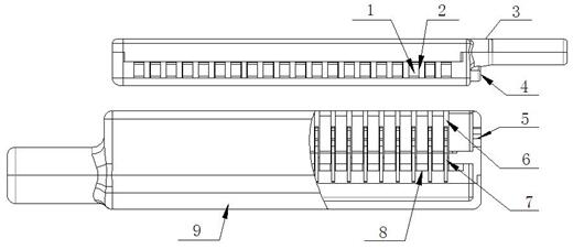
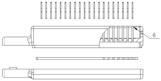
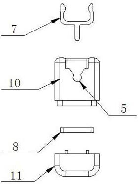
[0034] Such as Figure 5 As shown, when the electrode needs to be connected with the cable, it is only necessary to connect the electrode shell with the terminal with the cable shell with the card, so that the terminal contacts the two ends of the card, the card is stretched by the terminal and the terminal is clamped tightly, and the contact effect is good. And contact at both ends can avoid poor contact or no contact phenomenon.
Login to View More PUM
 Abstract
The invention relates to the technical field of medical instruments, in particular to a brain electrode connector. The brain electrode connector comprises an electrode shell connected with an electrode and a cable shell connected with a cable, a plurality of terminal grooves used for clamping terminals are formed in the electrode shell, and a circuit board and a card are arranged in the cable shell; the card is arranged in a card groove in the cable shell and comprises an open clamping end and a connecting end connected with the circuit board, and the opening clamping end of the card has certain elasticity and clamps at the two sides of the terminal. The brain electrode connector is suitable for the transmission of tiny signals and has the effects of moderate clamping force, convenience in plugging and unplugging and stable contact; a multichannel wire can control the distance between the adjacent card and the terminal through the clamping groove of the shell, and the requirement for smaller-size connection of the multichannel electrode can be met; meanwhile, the terminal can be made of stainless steel, titanium alloy and other materials, and spot welding is facilitated; and the terminal also can be made of the materials, such as copper alloy, etc., and adopts the tin soldering; and the card is made of beryllium copper and is good in elasticity and long in service life.
Description
technical field [0001] The invention relates to a connector, in particular to a brain electrode connector. Background technique [0002] Medically, the multi-point connector is used to detect deep EEG signals, and has all the characteristics of traditional deep electrodes and positioning diagnosis functions. [0003] Most of the common small multi-point connectors are of three types: female row, pogo pin, and shrapnel. [0004] Mother row; single row is easy to break when there are many points, and it is too long. Difficult to plug and unplug when double row, easy to bend. The female row has a matching male end, and the connection between the two and the electrodes is made by soldering. Connect the 2.54-pitch pin header with a maximum current of 3A and a voltage of 500VAC. Its contact is stable and can be used for μV level signal transmission. [0005] Pogo pins: easy to plug and unplug, and the contact stability is not as good as pin headers. Generally, the rated volta...
Claims
Login to View More Application Information
Patent Timeline
 Patent Type & AuthorityApplications(China)
IPC IPC(8): H01R13/40H01R13/15H01R13/03A61B5/291A61B5/274
CPCH01R13/40H01R13/15H01R13/03A61B5/274A61B5/291
Inventor丁汉卿蒋军庭张新国
OwnerCHANGZHOU RUISHENAN MEDICAL DEVICES