Eureka AIR delivers breakthrough ideas for toughest innovation challenges, trusted by R&D personnel around the world.

Padlock fixing device for laser cutting of metal plate

A laser cutting and fixing device technology, which is applied in metal processing equipment, laser welding equipment, welding equipment, etc., can solve the problems of poor comprehensive adaptation of metal plates, inability to clamp and fix metal plates, and easy damage to the surface of metal plates. To avoid crushing, reduce trouble, and facilitate installation

Inactive Publication Date: 2018-10-26
WUXI YICHEN MOLD TECH
View PDF6 Cites 2 Cited by
  • Summary
  • Abstract
  • Description
  • Claims
  • Application Information

AI Technical Summary

Problems solved by technology

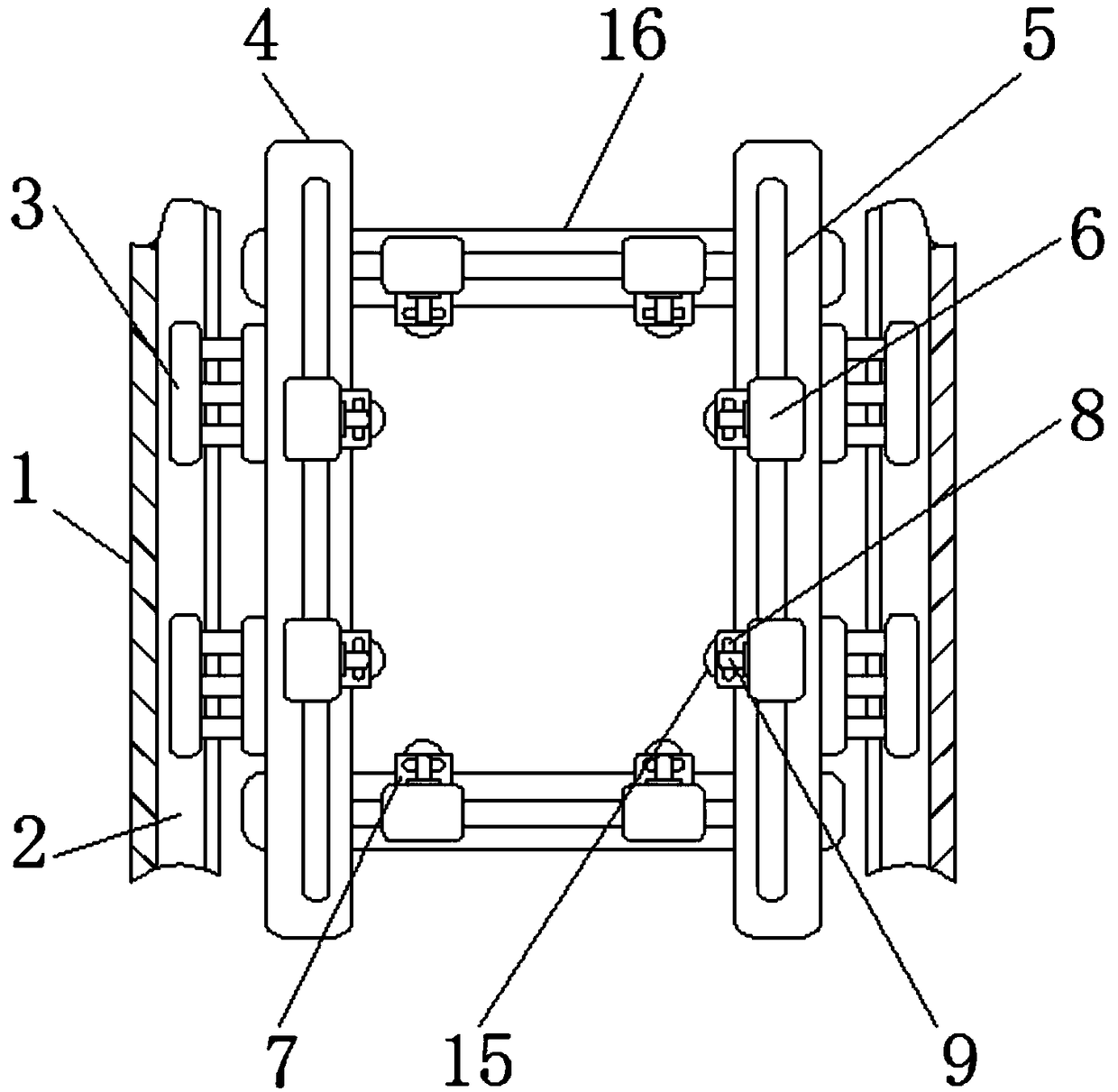
[0004] The purpose of the present invention is to provide a buckle lock fixing device for laser cutting of metal plates, to solve the problem that the metal plates need to be clamped during the installation process of the metal plates proposed in the above background technology, and the excessive clamping force will easily damage the metal plates On the surface, the comprehensive adaptation effect of the fixing device to the metal plate is poor, and the metal plate cannot be clamped and fixed according to the actual size of the metal plate, and the metal plate cannot be moved as a whole after installation, which is not convenient for installation

Method used


Image

  • Padlock fixing device for laser cutting of metal plate
  • Padlock fixing device for laser cutting of metal plate
  • Padlock fixing device for laser cutting of metal plate

Examples


Embodiment Construction

[0016] The following will clearly and completely describe the technical solutions in the embodiments of the present invention with reference to the accompanying drawings in the embodiments of the present invention. Obviously, the described embodiments are only some, not all, embodiments of the present invention. Based on the embodiments of the present invention, all other embodiments obtained by persons of ordinary skill in the art without making creative efforts belong to the protection scope of the present invention.

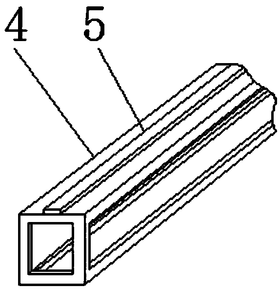
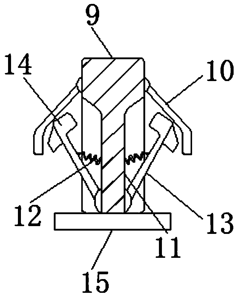
[0017] see Figure 1-3 , the present invention provides a technical solution: a buckle lock fixing device for laser cutting of metal plates, including a sliding track 1, a vertical support plate 4 and a buckle plate 9, the inside of the sliding track 1 is provided with a rail groove 2, and the rail groove The inner side of 2 is equipped with a moving block 3, the surface of the vertical support plate 4 is welded with a bar rail 5, and the vertical support plat...


PUM


Abstract

The invention discloses a padlock fixing device for laser cutting of a metal plate. The padlock fixing device comprises sliding rails, vertical support plates and buckle plates, and each sliding railis internally provided with a rail slot of which the inner side is provided with a movable block; the surface of each vertical support plate is welded with a bar rail, and the vertical support platesare located on the inner sides of the movable blocks; the middle of each bar rail is provided with clamping blocks of which the inner sides are fixedly provided with clamping plates, and the middle ofeach clamping plate is provided with a straight slot; the right and left sides of each buckle plate are each provided with a lift plate, and each buckle plate is located in the middle of the straightslot; grooves are fixedly formed in the positions below the buckle plates, and the outer sides of each groove are provided with springs of which the outer sides are provided with connecting plates; and the upper sides of the connecting plates are welded with buckle blocks, and holding plates are fixed below the connecting plates. The padlock fixing device for the metal plate is easy to install, and the clamping force is moderate; and the length and width can be adjusted according to the metal plate, and the adaption degree of the metal plate is higher.

Description

technical field [0001] The invention relates to the technical field of metal plate installation, in particular to a buckle lock fixing device for laser cutting of metal plates. Background technique [0002] Laser cutting of metal plates replaces traditional mechanical knives with invisible beams. It has the characteristics of high precision, fast cutting, not limited to cutting pattern restrictions, automatic typesetting to save materials, smooth incision, and low processing costs. [0003] There are many defects in the installation of existing metal plates. For example, the metal plate needs to be clamped during the installation process of the metal plate. Excessive clamping force is easy to damage the surface of the metal plate. The shapes and sizes of the metal plates are different. When installing and fixing, it is necessary to choose a suitable fixing device. The comprehensive adaptation effect of the fixing device on the metal plate is poor, and the metal plate cannot ...

Claims


Application Information

Patent Timeline
Patent Type & Authority Applications(China)
IPC IPC(8): B23K26/70B23K26/38
CPCB23K26/38B23K26/702
Inventor 钱根来张发根
Owner WUXI YICHEN MOLD TECH
Why Eureka
Eureka Blog
Learn More