
Collection box and liquid supply device

A collection box and liquid supply technology, which is applied to metal processing machinery parts, maintenance and safety accessories, metal processing equipment, etc., can solve the problem of low chip cleaning efficiency, improve chip collection and cleaning efficiency, and solve chip cleaning efficiency. Effect

Inactive Publication Date: 2020-10-30
ZHUHAI GREE INTELLIGENT EQUIP CO LTD +1
View PDF7 Cites 3 Cited by
  • Summary
  • Abstract
  • Description
  • Claims
  • Application Information

AI Technical Summary

Problems solved by technology

[0005] The main purpose of the present invention is to provide a collection box and a liquid supply device to solve the problem of low chip cleaning efficiency in the collection box above the water tank of the machine tool in the prior art

Method used


Image

  • Collection box and liquid supply device
  • Collection box and liquid supply device
  • Collection box and liquid supply device

Examples


Embodiment Construction

[0032] It should be noted that, in the case of no conflict, the embodiments in the present application and the features in the embodiments can be combined with each other. The present invention will be described in detail below with reference to the accompanying drawings and examples.

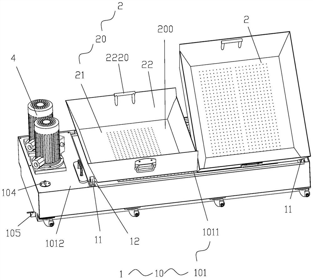
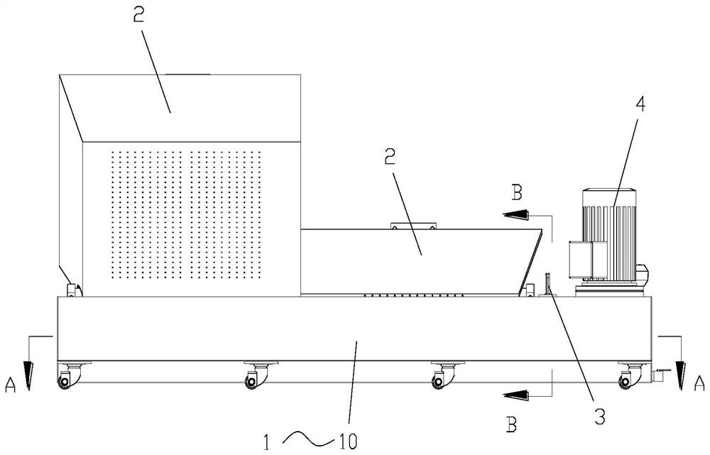
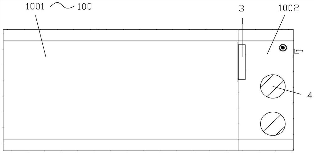
[0033] like Figure 1 to Figure 9 As shown, the present invention provides a collection box, comprising: a box body 20, the box body 20 has an accommodating chamber 200 and an opening communicated with the accommodating chamber 200; A plurality of first filter holes 210 are provided on it; wherein, the box body 20 has a rotating part 23 for rotatably connecting with the supporting platform 101 , so as to dump the substances in the accommodating chamber 200 by turning the box body 20 .

[0034] The collection box rotatably connected to the support platform 101 provided by the present invention is used for filtering, collecting chips and allowing the cutting fluid to flow to the bottom of the bo...


PUM


Abstract

The invention provides a collection box and a liquid supply device. The collection box comprises a box body, wherein the box body is provided with a containing cavity and an opening part communicatingwith the containing cavity, the box body comprises a bottom plate located below the containing cavity, and a plurality of first filtering holes are formed in the bottom plate. The box body is provided with a rotating part rotatably connected with a supporting table top to pour the substance located in the containing cavity by turning over the box body. According to the collection box, the problemof low chip removal efficiency in the collection box above a machine tool water tank in the prior art is solved.

Description

technical field [0001] The invention relates to the field of machine tools, in particular to a collection box and a liquid supply device. Background technique [0002] CNC machine tools are widely used in the field of cutting processing and are one of the important equipment for metal cutting processing. [0003] As the application range of CNC machine tools is becoming wider and wider, among them, for CNC machine tools using water tanks, a very important problem is that during the cutting process, chips are collected in the collection box above the water tank, and then manual use of shovels is required These chips need to be removed with a shovel several times to complete the removal, and often cannot be completely removed, and the cleaning efficiency is low. [0004] At the same time, fine iron filings will enter the filter area under the water tank, and then enter the water storage area where the water pump operates. After a long time, the water storage area needs to be ...

Claims


Application Information

Patent Timeline
Patent Type & Authority Applications(China)
IPC IPC(8): B23Q11/00B23Q11/10
CPCB23Q11/00B23Q11/10
Inventor 郭雷雷杨建新林茂康张秀峰张天翼
Owner ZHUHAI GREE INTELLIGENT EQUIP CO LTD
Learn More