
A silver teacup inner wall polishing device

A technology for polishing devices and teacups, which is applied in the direction of grinding drive devices, grinding/polishing equipment, surface polishing machine tools, etc., can solve the problems of cumbersome operation process, low work efficiency, and manpower consumption, and achieve simple operation and improved work efficiency. Efficiency and manpower saving effect

Active Publication Date: 2022-07-22
浙江康福海工贸有限公司
View PDF0 Cites 0 Cited by
  • Summary
  • Abstract
  • Description
  • Claims
  • Application Information

AI Technical Summary

Problems solved by technology

[0006] In order to overcome the shortcomings of the above-mentioned method, such as cumbersome operation process, low work efficiency, and relatively labor-intensive operation, the technical problem to be solved by the present invention is to provide a silver teacup that is easy to operate, can improve work efficiency, and saves manpower Inner wall polishing device

Method used

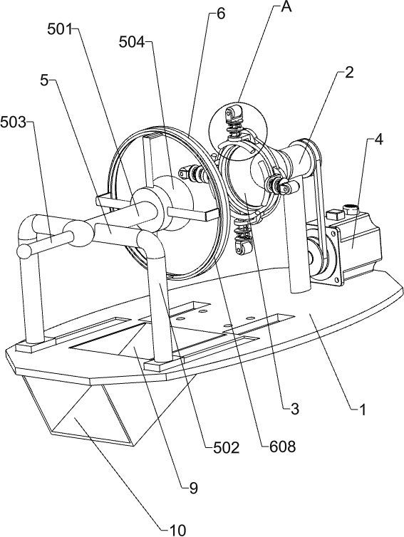

Image

  • A silver teacup inner wall polishing device
  • A silver teacup inner wall polishing device
  • A silver teacup inner wall polishing device

Examples


Embodiment 1

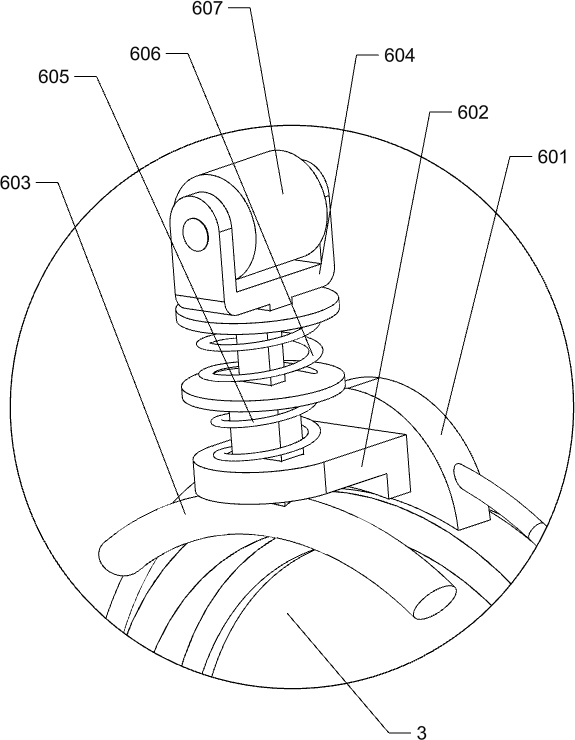
[0024] A silver teacup inner wall polishing device, such as Figure 1-4 As shown, it includes a bottom plate 1, a mounting bushing 2, a tapered holder 3 and a motor 4. A mounting bushing 2 is connected to the front side of the top of the bottom plate 1, and a conical socket 3 is rotatably connected in the mounting bushing 2. The bottom plate 1. A motor 4 is installed on the front side of the top. The output shaft of the motor 4 is connected to the tapered holder 3 in a driving manner. It also includes a polishing component 5 and a clamping component 6. The rear side of the top of the bottom plate 1 is provided with a polishing component 5. The tapered holder A clamping assembly 6 is provided between the polishing assembly 3 and the polishing assembly 5 .

[0025] The polishing assembly 5 includes a first push rod 501, an L-shaped sliding rod 502, a handle 503 and a polishing ball 504. An L-shaped sliding rod 502 is slidably connected to the rear side of the top of the bottom p...

Embodiment 2

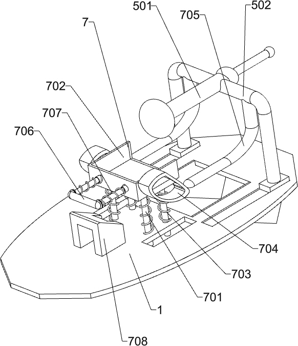
[0029] On the basis of Example 1, as Figure 4 As shown, it also includes a discharge assembly 7, and the discharge assembly 7 includes a vertical rod 701, a placing frame 702, a rising spring 703, a sloping plate 704, a second push rod 705, a U-shaped rod 706, a return spring 707 and a wedge-shaped seat 708, a plurality of vertical rods 701 are slidably connected in the middle of the top of the bottom plate 1, a placing frame 702 is connected between the tops of the plurality of vertical rods 701, a rising spring 703 is connected between the placing frame 702 and the bottom plate 1, and the left and right sides of the placing frame 702 are connected Both are connected with a sloping plate 704, and the left and right sides of the L-shaped slide bar 502 are connected with a second push rod 705. The second push rod 705 cooperates with the inclined plate 704. The front side of the placing frame 702 is slidably connected with a U-shaped rod 706. A return spring 707 is connected be...


PUM


Abstract

The invention relates to a polishing device, in particular to a polishing device for the inner wall of a silver teacup. The technical problem to be solved by the present invention is to provide a silver teacup inner wall polishing device that is easy to operate, can improve work efficiency, and save labor. In order to solve the above technical problems, the present invention provides such a silver teacup inner wall polishing device, which includes: a bottom plate, the top side of which is connected with a mounting bushing; It is installed on the top of the bottom plate near the side of the installation bushing, and the output shaft of the motor is connected with the tapered holder; the polishing component is arranged on the top of the bottom plate; the clamping component is arranged between the tapered holder and the polishing component . In the invention, the silver teacup is polished through the coordinated operation of the polishing component, the clamping component and the motor, so as to achieve the effect of polishing the silver teacup.

Description

technical field [0001] The invention relates to a polishing device, in particular to a polishing device for the inner wall of a silver teacup. Background technique [0002] A teacup is a utensil for holding tea. Water comes from a teapot, poured into the teacup, and then served to the guests. Tea cups are divided into two sizes: small cups are mainly used for sipping oolong tea, also called tea cups, which are used in conjunction with smelling cups. Silver teacup is a kind of teacup. The teacup made of silver has the functions of sterilization, antibacterial, disease treatment, antiseptic preservation, etc. The inner wall of the silver teacup needs to be polished after production. [0003] At present, the method of polishing the silver teacup is usually to manually place the silver teacup on the rotating device to make the silver teacup rotate, and then use a polishing cloth to stick the silver teacup for polishing. The operation is more labor-intensive. [0004] Therefor...

Claims


Application Information

Patent Timeline
Patent Type & Authority Patents(China)
IPC IPC(8): B24B29/02B24B41/00B24B41/06B24B47/00B24B47/12B24B47/22
CPCB24B29/02B24B41/062B24B47/12B24B47/22B24B41/005B24B47/00
Inventor 朱华峰
Owner 浙江康福海工贸有限公司
Learn More