An edge throwing device for acrylic board processing

A technology of support seat and guide rail, used in metal processing, applications, household appliances, etc.

Active Publication Date: 2022-04-26
四川渝拓橡塑工程有限公司
View PDF7 Cites 0 Cited by
  • Summary
  • Abstract
  • Description
  • Claims
  • Application Information

AI Technical Summary

Problems solved by technology

[0004] In order to overcome the shortcomings of manually aligning the fixed frame when placing the acrylic board, and manually adjusting the acrylic board after placement, the technical problem of the present invention is to provide an acrylic board that can automatically adjust and position the acrylic board. , so that the position of the acrylic plate to be polished is aligned with the edge polishing device for acrylic plate processing of the polishing equipment

Method used


Image

  • An edge throwing device for acrylic board processing
  • An edge throwing device for acrylic board processing
  • An edge throwing device for acrylic board processing

Examples


Embodiment 1

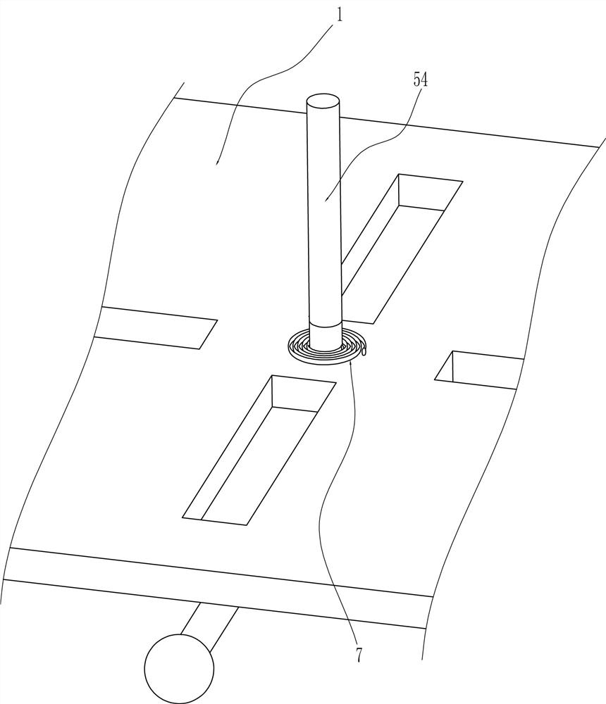
[0025] An edge throwing device for acrylic plate processing, such as Figure 1-7 As shown, it includes a support base 1 and a chassis 2. The top of the support base 1 is connected to the chassis 2, and also includes a rubber disc 3, a moving component 4 and a positioning component 5. The top of the chassis 2 is connected to the rubber disc 3 in a rotatable manner. There are four slide slots 31 evenly spaced along the circumference, a moving assembly 4 is provided between the chassis 2 and the support base 1 , and a positioning assembly 5 is provided between the slide slots 31 and the support base 1 .

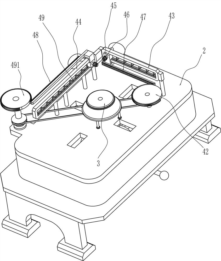
[0026] The moving assembly 4 includes a drive motor 41, a first tooth-missing gear 42, a first guide rail 43, a second guide rail 44, a first slider 45, a spray gun 46, a first rack 47, a second rack 48, and a return spring 49 and the second tooth-missing gear 491, a drive motor 41 is installed on the top of the support base 1, the output shaft of the drive motor 41 passes throu...

Embodiment 2

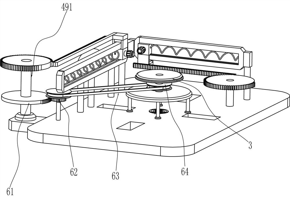
[0030] On the basis of Example 1, such as Figure 8 As shown, a rotating assembly 6 is also included, and the rotating assembly 6 includes a sector gear 61, a transmission gear 62, a flat belt 63 and a pulley 64, the sector gear 61 is connected to the second missing tooth gear 491, and the top of the support base 1 is connected in a rotational manner There is a transmission gear 62 meshing with the sector gear 61 , a pulley 64 is connected to the transmission gear 62 and the rubber disc 3 , and a flat belt 63 is wound between the two pulleys 64 .

[0031] When the second missing tooth gear 491 rotates, it drives the sector gear 61 to rotate together. When the second tooth missing gear 491 disengages from the second rack 48, the sector gear 61 meshes with the transmission gear 62. At this time, the sector gear 61 continues to rotate to drive The transmission gear 62 rotates, and the transmission gear 62 rotates through the pulley 64 and the flat belt 63 to drive the rubber disc...


PUM


Abstract

The invention relates to an edge throwing device, in particular to an edge throwing device for processing acrylic boards. The technical problem of the present invention is how to design an edge polishing device for acrylic plate processing that can automatically adjust the acrylic plate and position the acrylic plate so that the position of the acrylic plate to be polished is aligned with the polishing equipment. An edge throwing device for acrylic board processing, including a support base, the top of which is connected to an organic case, and four slide grooves are evenly spaced along the circumference of the case; a rubber disc is rotatably connected to the top of the case; The component is installed between the chassis and the support base. The invention can clean the burrs on the side of the acrylic plate through the operation of the moving component, thereby achieving the effect of polishing the acrylic plate.

Description

technical field [0001] The invention relates to an edge throwing device, in particular to an edge throwing device for processing acrylic boards. Background technique [0002] Acrylic, also known as specially treated plexiglass, is a replacement product of plexiglass. The light box made of acrylic has good light transmission performance, pure color, rich color, beautiful and flat, taking into account both day and night effects, long service life, and does not affect use, etc. features. In addition, acrylic sheets can be perfectly combined with aluminum-plastic sheet profiles and advanced screen printing to meet the needs of merchants. After the acrylic sheet is manufactured, there will be some burrs on the side, which are easy to stick and affect the installation. The burrs need to be polished. [0003] After searching, the authorized patent publication number is CN206519821U, which discloses a simple acrylic plate polishing device, including a walking frame and a fixed fram...

Claims


Application Information

Patent Timeline
Patent Type & Authority Patents(China)
IPC IPC(8): B29C37/02B26F3/16B26D7/01B26D7/06B29L7/00
CPCB29C37/02B26F3/16B26D7/015B26D7/0625B29L2007/002
Inventor 陈伟超
Owner 四川渝拓橡塑工程有限公司
Why Eureka
Try Eureka