Wing rib stamping micro-contact grinding device in aircraft manufacturing

A technology for aircraft manufacturing and wing ribs, which is applied in the field of wing rib stamping micro-contact grinding devices, which can solve problems such as damage, inconvenience, and grinding of wing ribs, and achieve the effect of easy grinding and increased stability

Inactive Publication Date: 2021-10-26
何怀彬
View PDF0 Cites 1 Cited by
  • Summary
  • Abstract
  • Description
  • Claims
  • Application Information

AI Technical Summary

Problems solved by technology

[0002] In aircraft manufacturing, it is necessary to punch the plate into a formwork pattern and then bend it. In order to stabilize the plate during punching, some small connection points are reserved between the formwork and the plate. After punching, the connection points need to be cut off. After the mold is removed, the connection points need to be polished to prevent the size of the drawing from being affected because the wings need to be joined together. Grinding, the ribs will be damaged if you do not pay attention, so a device is needed to assist the ribs to stabilize when the micro-connection points of the ribs are polished

Method used


Image

  • Wing rib stamping micro-contact grinding device in aircraft manufacturing
  • Wing rib stamping micro-contact grinding device in aircraft manufacturing
  • Wing rib stamping micro-contact grinding device in aircraft manufacturing

Examples


Embodiment Construction

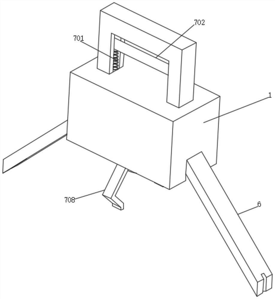
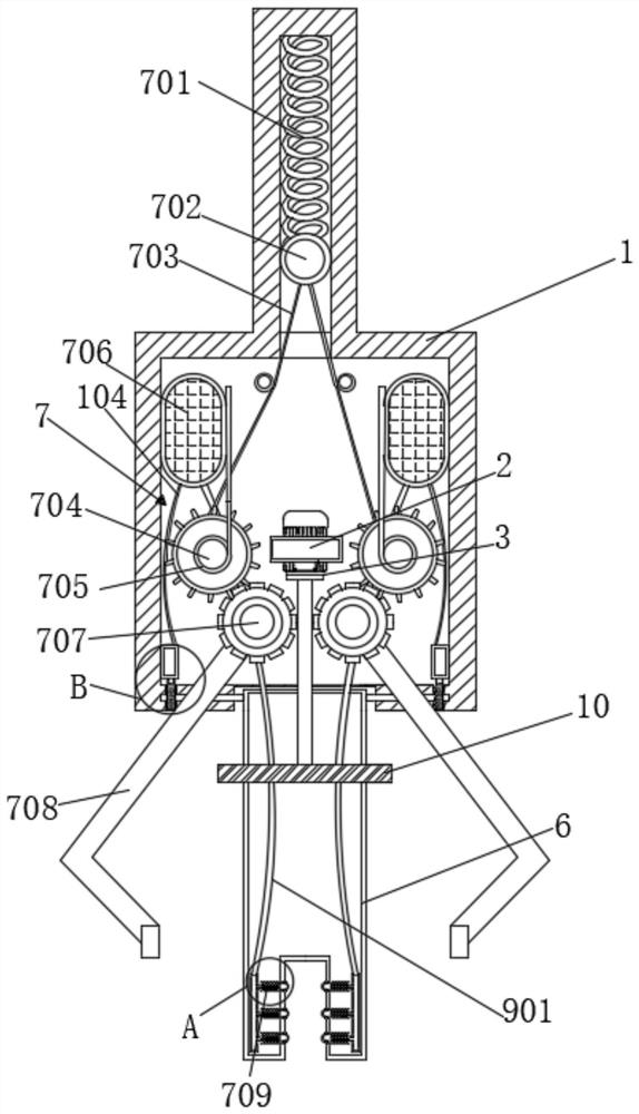
[0023] Such as Figure 1-6 As shown, the present invention provides a technical solution: a wing rib stamping micro-contact grinding device in aircraft manufacturing, including a fixed housing 1, the bottom of the fixed housing 1 is provided with an opening, and the middle part of the inner wall of the fixed housing 1 is fixedly connected There is a fixed block 2, and the middle part of the fixed block 2 is embedded with a motor 3. The lower end of the output rod of the motor 3 runs through the bottom of the fixed housing 1 and is fixedly connected with a grinding block 10. The inner wall of the bottom of the fixed housing 1 is plugged with the first rotating rod 4. , the left end of the first rotating rod 4 is plugged into the bottom inner wall of the fixed block 2, the left side of the outer wall of the first rotating rod 4 is rotationally connected with the inner wall of the fixed housing 1 through a bearing, and the left outer wall of the first rotating rod 4 is fixedly con...


PUM


Abstract

The invention relates to the technical field of aircraft manufacturing and discloses a wing rib stamping micro-contact grinding device in the aircraft manufacturing. The wing rib stamping micro-contact grinding device comprises a fixed shell, a fixed block is fixedly connected to the middle of the inner wall of the fixed shell, a motor is fixedly embedded in the middle of the fixed block, the lower end of an output rod of the motor penetrates through the bottom of the fixed shell to be fixedly connected with a grinding block, a first rotating rod is connected to the inner wall of the bottom of the fixed shell in an inserted manner, the left end of the first rotating rod is connected to the inner wall of the bottom of the fixed block in an inserted manner, in use, first air bags are extruded through extrusion plates, gases in the first air bags are extruded into buffer boxes through first air pipes, the buffer boxes convey the gases into sliding grooves through the sliding grooves, rubber blocks are pushed by the gases to move rightwards, second springs are stretched and deformed, the rubber blocks move towards the outer side of a hollow clamping plate to clamp a wing rib plate, a whole machine body cannot shake left and right relative to the wing rib plate, the stable effect is achieved, and the wing rib plate can be conveniently ground through the grind block.

Description

technical field [0001] The invention relates to the technical field of aircraft manufacturing, in particular to a wing rib stamping micro-contact grinding device in aircraft manufacturing. Background technique [0002] In aircraft manufacturing, it is necessary to punch the plate into a formwork pattern and then bend it. In order to stabilize the plate during punching, some small connection points are reserved between the formwork and the plate. After punching, the connection points need to be cut off. After the mold is removed, the connection points need to be polished to prevent the size of the drawing from being affected because the wings need to be joined together. Grinding will damage the ribs if you don’t pay attention, so a device is needed to assist the ribs to stabilize when the micro-connection points of the ribs are polished. Contents of the invention [0003] The purpose of the present invention is to provide a wing rib stamping micro-joint grinding device in ...

Claims


Application Information

Patent Timeline
Patent Type & Authority Applications(China)
IPC IPC(8): B24B23/00B24B9/04B24B41/06B24B41/00B24B41/02B24B47/12B24B55/00
CPCB24B23/00B24B9/04B24B41/06B24B41/007B24B41/02B24B47/12B24B55/00
Inventor 何怀彬
Owner 何怀彬
Why Eureka
Try Eureka