
Driving device, transmission device and power tool for linear motion

A technology of linear motion and driving device, applied in nailing tools, manufacturing tools, nailing staple tools, etc., can solve the problems of inability to effectively realize driving, reduce output effect, force offset, etc., and achieve flexibility in application methods , optional strong effect

Pending Publication Date: 2020-10-30
苏州品匠机电技术有限公司
View PDF3 Cites 2 Cited by
  • Summary
  • Abstract
  • Description
  • Claims
  • Application Information

AI Technical Summary

Problems solved by technology

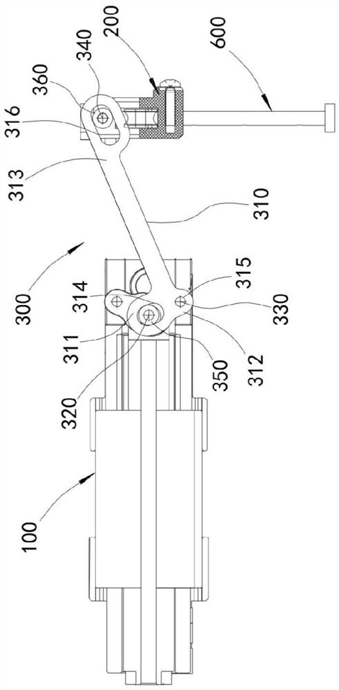
[0004] In this structure, the second end 1021 of the lever is pivotally connected to the connecting rod 15, and its second end 1011 is inserted into the hollow part 191 of the slider. The connecting rod 15 drives the lever to rotate around the fulcrum P, but this In this structure, the second end 1021 moves in an arc, while the connecting rod 15 can only move in a straight line, so the movement of the connecting rod 15 and the second end of the lever will interfere, which will easily lead to force deviation. The rotation angle of the lever is greatly limited, resulting in limited output force and speed, and even unable to effectively drive
[0005] In addition, when the second end portion 1011 is inserted into the hollow portion 191, the second end portion 1011 will impact the movement of the slider 19 during operation, which increases the vibration of the slider and reduces the output effect.
[0006] At the same time, in this structure, the reaction force of the lever will generate a certain tilting force on the side wall of the power source (motor), resulting in asymmetrical magnetic field of the power source and shortened life.

Method used


Image

  • Driving device, transmission device and power tool for linear motion
  • Driving device, transmission device and power tool for linear motion
  • Driving device, transmission device and power tool for linear motion

Examples


Embodiment Construction

[0047] Objects, advantages and features of the present invention will be illustrated and explained by the following non-limiting description of preferred embodiments. These embodiments are only typical examples of applying the technical solutions of the present invention, and all technical solutions formed by adopting equivalent replacements or equivalent transformations fall within the protection scope of the present invention.

[0048] In the description of the scheme, it should be noted that the terms "center", "upper", "lower", "left", "right", "front", "rear", "vertical", "horizontal", " The orientation or positional relationship indicated by "inner", "outer", etc. is based on the orientation or positional relationship shown in the drawings, and is only for the convenience of description and simplification of description, rather than indicating or implying that the device or element referred to must have a specific orientation , constructed and operated in a particular or...


PUM


Abstract

The invention discloses a driving device, a transmission device and a power tool for linear motion. The driving device comprises a power source, an actuator and a transmission part driven by the powersource to reciprocate linearly, the transmission part comprises an input part, a support part and an output part, a first sliding groove is formed in one of the input part and the support part, a shaft hole is formed in the other one of the input part and the support part, a second sliding groove or a circular hole is formed in the position of the output part, a driving shaft driven by the powersource to reciprocate linearly is arranged in one of the first sliding groove and the shaft hole, a fixed support shaft is arranged in the other one of the first sliding groove and the shaft hole, a driven shaft connected with the actuator is arranged in the second sliding groove or the circular hole, and all shafts are parallel to each other. According to the scheme, when the power source drivesthe transmission part, the shafts can move in the first sliding groove, so that the rotation of the transmission part is not restricted, the second sliding groove always exerts downward pressure or upward lifting force on an output shaft, the impact on the actuator can be reduced, the vibration of the actuator is reduced, and the impact strength is increased.

Description

technical field [0001] The invention relates to the field of power tools, in particular to a driving device, a transmission device and a power tool for linear motion. Background technique [0002] Nail guns are widely used in construction, decoration, furniture manufacturing, advertising decoration and other fields; they include pneumatic nail guns and electric nail guns, among which pneumatic nail guns need to be powered by an air pump and connected to an air supply line, which is difficult to carry and use. cause inconvenience. [0003] Electric nail guns are easy to carry and use because they only need to be connected to electricity, so they are more and more popular in the market. Thereby driving the striker to punch the nail, the nailing efficiency of the electromagnetic nail gun of this structure is higher, such as the electromagnetic nail gun disclosed by the authorized announcement numbers CN100553889C and CN105082065B, the power of the power source drives the slide...

Claims


Application Information

Patent Timeline
IPC IPC(8): B25C1/06B25C7/00
CPCB25C1/06B25C7/00
Inventor 胡方坤丁学明朱学超
Owner 苏州品匠机电技术有限公司
Learn More