Oil cylinder locking device

A locking device and oil cylinder technology, applied in the direction of fluid pressure actuating device, etc., can solve problems such as unreasonable force, difficult to adapt to locking, complex structure, etc., achieve uniform and reasonable force, solve locking problem, and strong selectivity Effect

Active Publication Date: 2012-12-26
POWERCHINA ZHONGNAN ENG
View PDF10 Cites 10 Cited by
  • Summary
  • Abstract
  • Description
  • Claims
  • Application Information

AI Technical Summary

Problems solved by technology

However, the patent is unreasonable in the force along the main force-bearing couple, and the structure is relatively complicated, so it is difficult to adapt to the locking of the hydraulic hoist cylinder of the Liyang tail water accident gate.

Method used


Image

  • Oil cylinder locking device
  • Oil cylinder locking device
  • Oil cylinder locking device

Examples


Embodiment Construction

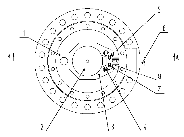
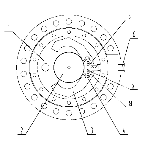
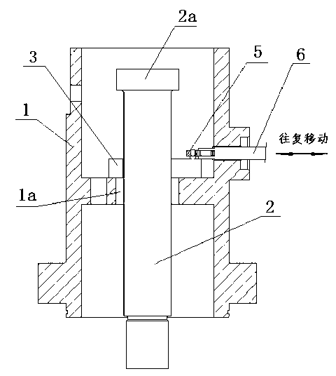
[0035] A cylinder locking device, such as figure 1 As shown, it mainly includes a locking seat 1, a locking column 2, a locking pawl 3, a pin shaft 4, a transmission plate 5 and a push-pull rod 6. Wherein the locking seat 1 is connected with the cylinder body through connecting bolts, the locking column 2 is connected with the piston rod through threads, and the push-pull rod 6 is integrated with the main driving rod of the servo device (which can be an oil cylinder or an electric push rod). The locking state of the cylinder locking device is as follows: figure 1 As shown, the released state is as figure 2 shown. The locking claw 3 is installed between the locking column 2 and the locking seat 1 and can limit the downward movement of the locking column 2; the locking claw 3 is driven by a servo device to lock or release, and when the locking claw 3 is released, the locking column 2 can Relative to the locking seat 1, it moves up and down freely. When the locking claw 3 i...


PUM


Abstract

The invention discloses an oil cylinder locking device. In order to realize the safe and fast locking goal of an oil cylinder of a gate hydraulic hoist, the oil cylinder locking device comprises a locking seat, a locking post and a locking claw, wherein the locking seat is connected with a cylinder body, the locking post is arranged in the locking seat and is connected with a piston rod, the locking claw is arranged between the locking post and the locking seat and can limit the downward movement of the locking post, the locking claw is driven by a servo device to be locked or released, when the locking claw is released, the locking post can freely and vertically move relative to the locking seat, and when the locking claw is locked, a locking post head positioned at the upper part of the locking post is placed on the locking claw. The oil cylinder locking device has the advantages that the stress along main stress coupling elements (the locking post and the locking claw) is uniform and reasonable, a servo mechanism is compact, the servo stroke is short, the servo motive power source selectivity is high, and the locking problem of the oil cylinder of the Liyang tail water accident gate hydraulic hoist is solved.

Description

technical field [0001] The invention relates to an oil cylinder locking device. Background technique [0002] Due to the needs of the overall layout, the hydraulic hoist cylinder of the Liyang tail water accident gate must be equipped with a locking device. [0003] Chinese patent ZL201020222977.5 discloses a hydraulic cylinder locking device, including a locking rod, a locking block and a locking cylinder that drives the locking block to move. The locking rod is arranged in the main cylinder and is fixedly connected with the piston rod of the main cylinder. There is a locking groove on the locking rod, and a locking block guide groove is opened on the cylinder head of the main oil cylinder. The locking block guide groove is perpendicular to the locking groove, and the locking block guide groove and the locking groove are connected, and the locking block and the locking block guide groove are slidably connected. . However, this patent is unreasonable in the force along the...

Claims


Application Information

Patent Timeline
Patent Type & Authority Applications(China)
IPC IPC(8): F15B15/26
Inventor 左长新袁长生虞喜泉蒋立新
Owner POWERCHINA ZHONGNAN ENG
Why Eureka
Try Eureka