Finned tube type heat converter of air conditioner

A technology for tubular heat exchangers and air conditioning fins, applied in heat exchange equipment, tubular elements, lighting and heating equipment, etc., can solve the problems of low heat exchange performance, high heat exchange performance, and no competitiveness. Achieve the effect of low cost, high heat exchange efficiency and strong selectivity

Active Publication Date: 2008-12-03
HAIER GRP CORP +1
View PDF1 Cites 10 Cited by
  • Summary
  • Abstract
  • Description
  • Claims
  • Application Information

AI Technical Summary

Problems solved by technology

[0024] The technical problem to be solved by the present invention is that the finned tube heat exchanger of the existing small diameter tube air conditioner is low in price, but the heat exchange performance is not high; the finned tube heat exchanger of the large diameter tube air conditioner can exchange heat The performance is high, but the cost is also high, and it has no competitiveness compared with competitors. In view of these shortcomings, a small-diameter tube air conditioner finned tube heat exchanger with high heat exchange efficiency is provided.

Method used


Image

  • Finned tube type heat converter of air conditioner
  • Finned tube type heat converter of air conditioner
  • Finned tube type heat converter of air conditioner

Examples


Embodiment 1

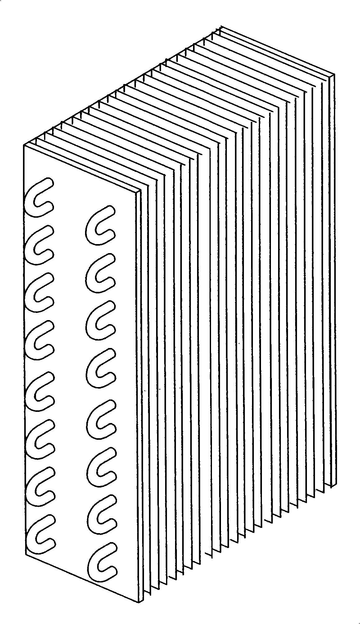
[0066] Figure 5 , 6 It is a schematic diagram of the fin structure of Embodiment 1 of the fin-tube heat exchanger of the present invention. The fins described in this embodiment are corrugated fins, and the corrugated fins are V-shaped corrugated fins 11. The V-shaped corrugated fins 11 are flat fins pressed into a plurality of continuous V shapes, as shown in the figure. The embodiment pays attention to extruding four V shapes. Through the test, under the condition that the fin spacing d is 1.2 to 1.65 mm, the spacing A of the connecting holes is 21 mm, and the width C of each V-shaped corrugation is 9.09 mm. When the height h is 1.2 mm, the best heat exchange effect can be obtained without generating noise and increasing wind resistance. At this time, the width B of the fin can be increased to 36.36mm. Considering the V-shaped relationship, the actual width is 37.6mm. The reason why the increased width does not produce vibration noise is that pressing the V-shaped corrug...

Embodiment 2

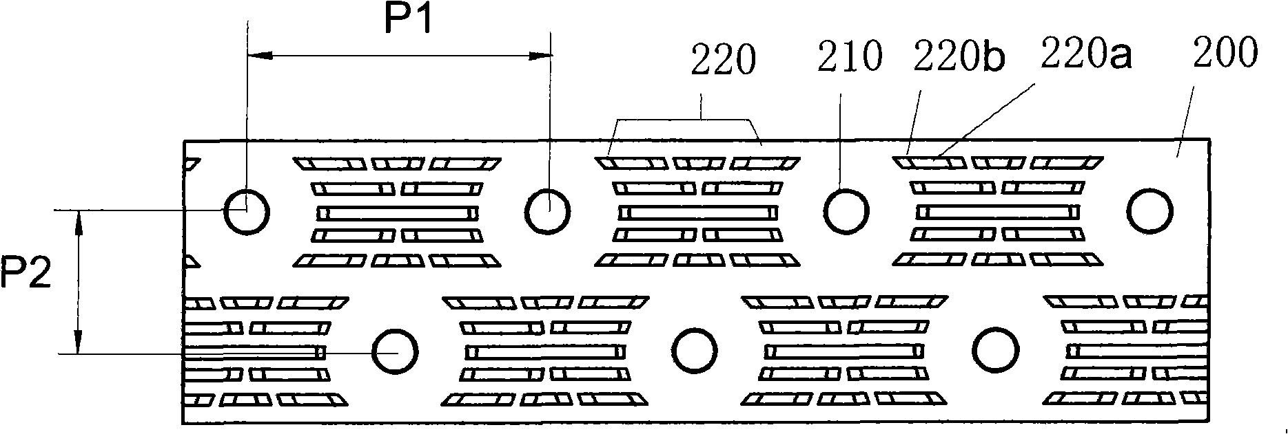
[0069] Figure 8 , 9 11 is a schematic diagram of the fin structure of Embodiment 2 of the fin-tube heat exchanger of the present invention. In the illustrated embodiment, the fins are slit fins 3, and the slit fins 3 are provided with a plurality of slits 30 in the spaces between the connection holes 10 of each row of the fins; The slit 30 is composed of a protruding section 31a and two upright sections 31b, and forms an opening facing the airflow direction between the fin plane, and the protruding sections of each slit protrude from the surface of each cooling fin in the same direction.

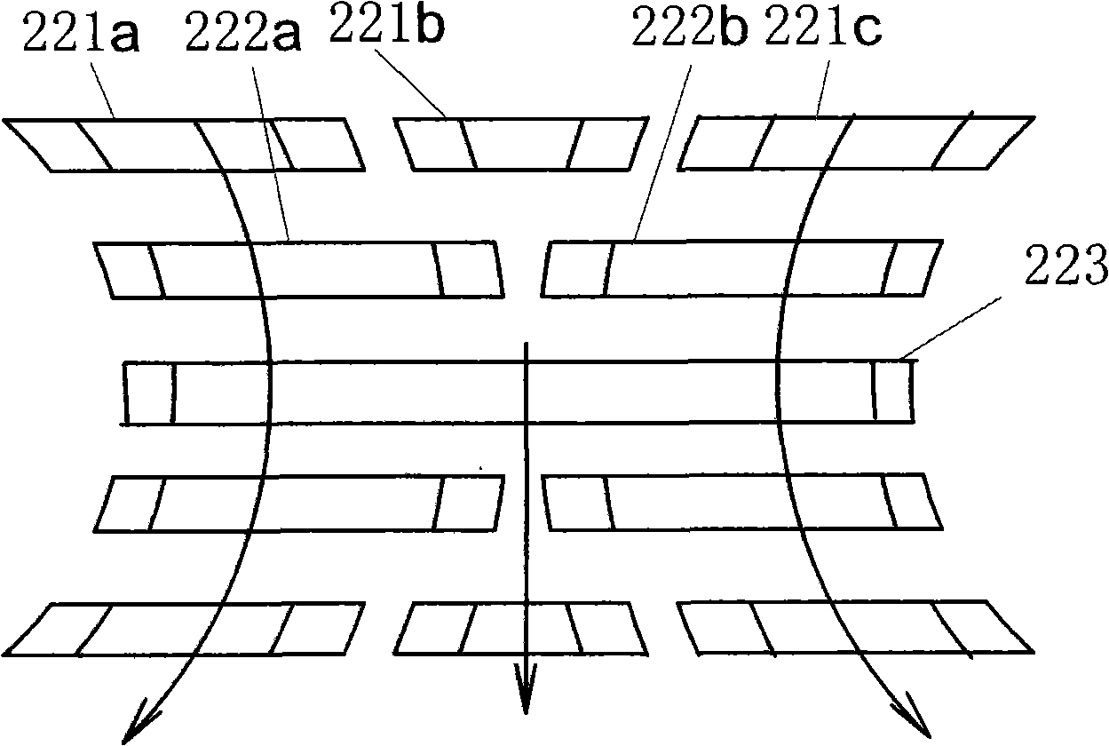
[0070] A plurality of slits between two adjacent connecting holes in each row of the slit fins form N rows, and each row has M slit units, and the center line of the two adjacent connecting holes and the vertical line of the line are X symmetrical arrangement. In the specific embodiment shown in the figure, the multiple slits between each row of connecting holes on the slit fin are arran...

Embodiment 3

[0075] Figure 13 It is a schematic diagram of the fin structure of Embodiment 3 of the present invention. In the illustrated embodiment, the fin is a slit fin 4, and the difference between the slit fin 4 and the slit fin 3 of Embodiment 2 is:

[0076] The plurality of slits between each row of connecting holes on the slit fin 4 are arranged in four rows in an X shape, wherein all four rows of slits are composed of one slit unit 411, 412; and the second and third rows The length of the slit unit is smaller than the length of the slit unit in the first and fourth rows, forming an X-shaped arrangement. in:

[0077] The projection of all the slit units in each row on the fin plane is an isosceles trapezoid; the projection on the plane perpendicular to the perpendicular bisector of the connecting hole center line is an isosceles trapezoid; The angle α between the perpendiculars of the lines connecting the holes is also 30°-38°, preferably 35°.

[0078] Figure 14 , 15 are th...


PUM


Abstract

The invention relates to a heat exchanger, in particular to an air conditioner finned tube type heat exchanger which comprises a plurality of U-shaped tubes and a plurality of fins sleeved parallelly on the U-shaped tubes, wherein the tube diameter of each U-shaped tube is 7mm; two rows of connecting holes for the U-shaped tubes to insert are formed on the fins, and the two rows of connecting holes on the fins are staggered in an equilateral triangle arrangement, namely the hole distance between two adjacent holes in the same row is equal to the hole distance between two adjacent holes in the different rows. The heat exchanger has the advantages of good heat exchanging effect, high energy efficiency ratio and low cost; and the heat exchanger carries out the optimization design for the dimensions and the sizes of fracture holes and the preference for the included angle between the two upright sections and the airflow direction, thereby effectively reducing the pressure loss on the air side, improving the heat transfer efficiency and meeting the requirement of the air conditioner with ever-growing energy efficiency ratio.

Description

technical field [0001] The invention relates to a heat exchanger, in particular to an air-conditioning fin-tube heat exchanger with low cost and high heat exchange efficiency. Background technique [0002] The structure of the finned tube heat exchanger used in the existing air conditioner is as follows: figure 1 As shown, it is mainly composed of a plurality of U-shaped elbows 1 and a plurality of fins 2 sleeved on the U-shaped elbows 1 in parallel. There are two main specifications of the heat sink used: [0003] (1) φ7*13.3, the copper tube used is small in diameter and low in cost. Due to the narrow fin width, small heat dissipation area, and poor heat transfer effect, it is difficult to meet the energy efficiency of air conditioners in the market, especially in Europe, Australia and other regions. requirements. [0004] (2) φ9.52*21.65, the diameter of the copper tube used is large, and the fin area is also large. Although the heat exchange effect is good, the cost i...

Claims


Application Information

Patent Timeline
Patent Type & Authority Applications(China)
IPC IPC(8): F28F1/30
Inventor 楚人震张守信张立智姚启媛
Owner HAIER GRP CORP
Why Eureka
Try Eureka