A steel bar installation device for reinforcement of plastic moisture-proof pallets
A technology for installing equipment and supporting plates, which is applied in the field of installing equipment with steel bars for reinforcement of plastic moisture-proof supporting plates. Sore hands, high work efficiency, and increased friction
- Summary
- Abstract
- Description
- Claims
- Application Information
AI Technical Summary
Problems solved by technology
Method used
Image
Examples
Embodiment 1
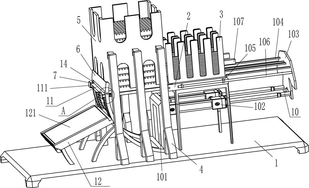
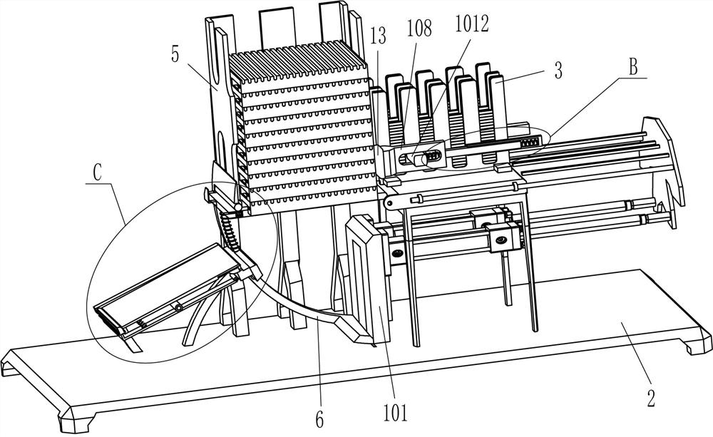
[0025] A steel bar installation equipment for reinforcement of plastic moisture-proof pallets, such as Figure 1-Figure 5 As shown, it includes a base 1, a worktable 2, a placing box 3, a support frame 4, a placing frame 5, an arc frame 6, an L-shaped limit plate 7, a sliding rod 8, a first spring 9, a pushing mechanism 10 and For the feeding mechanism 11, three support frames 4 are fixedly connected to the top of the base 1 at even intervals on both sides, and a placing frame 5 is fixedly connected between the inner ends of the six support frames 4. A workbench is fixed to the middle of the right side of the top of the base 1. 2. The top and front sides of the workbench 2 are evenly spaced and fixed with a placing box 3 that can place the steel bars. A pushing mechanism 10 is provided between the workbench 2 and the top of the base 1 and the placing box 3. The pushing mechanism 10 also In cooperation with the placing box 3, an arc-shaped frame 6 is fixed on the left side of t...
Embodiment 2
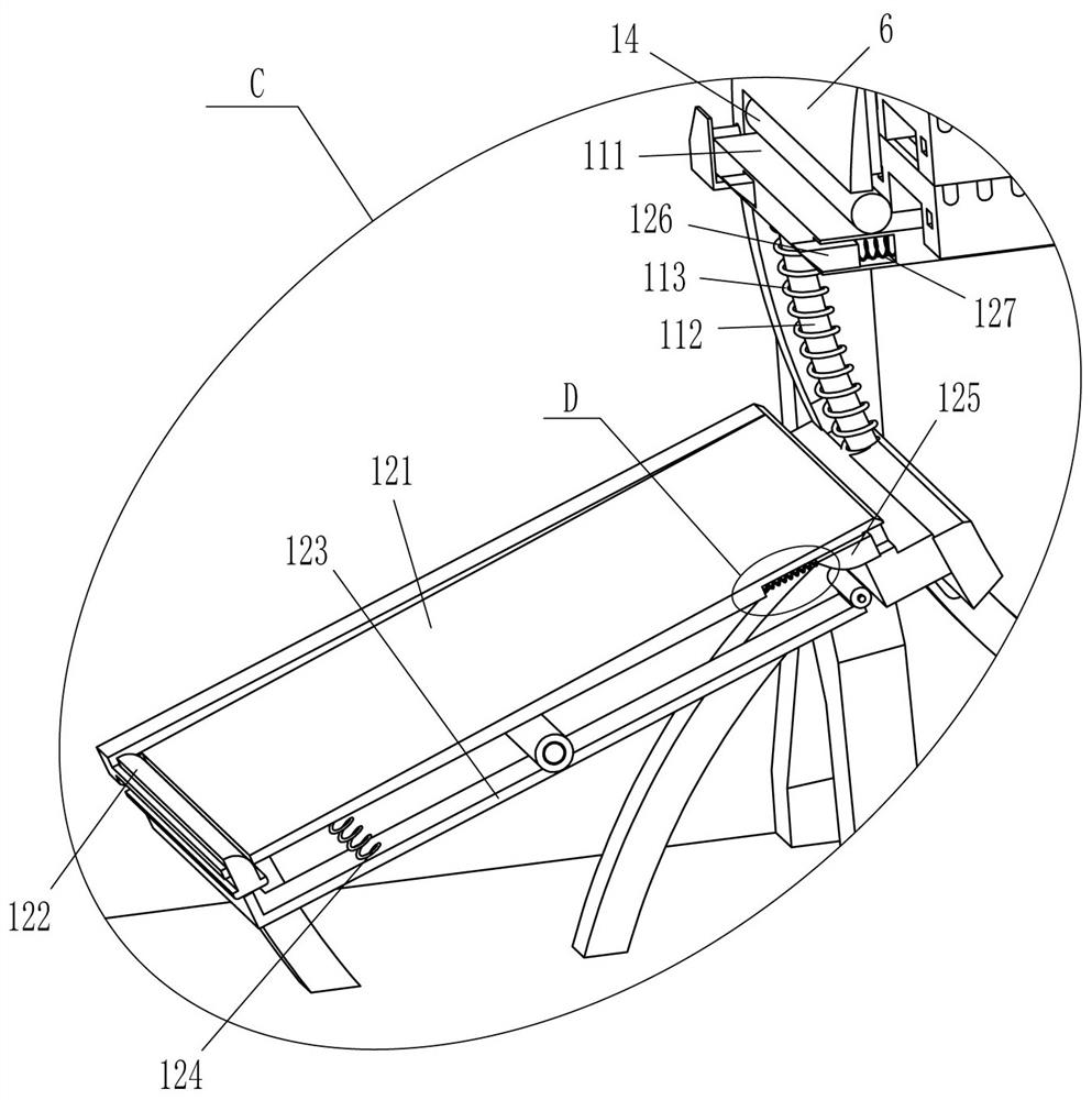
[0032] On the basis of Example 1, as figure 1 , figure 2 , Figure 5 and Image 6 As shown, it also includes a guide mechanism 12, and the guide mechanism 12 includes a guide frame 121, a trigger block 122, a u-shaped plate 123, a fifth spring 124, a push block 125, a wedge block 126, a sixth spring 127 and a seventh spring 128 A guide frame 121 is fixedly connected between the left side of the top of the base 1 and the middle part of the outer side surface of the arc-shaped frame 6. The right part of the guide frame 121 is symmetrically slidable with a push block 125. The left side of the push block 125 and the interior of the guide frame 121 A seventh spring 128 is connected between them. A wedge-shaped block 126 is symmetrically slidable in front and rear on the left side of the swing baffle 111. The wedge-shaped block 126 cooperates with the push block 125. The sixth spring 127, a trigger block 122 is slidably connected to the top left of the guide frame 121, and a u-s...
Embodiment 3
[0035] On the basis of Example 1 and Example 2, as figure 1 and figure 2 As shown, a rubber block 13 is also included, and the rubber block 13 is fixed on the outer left side of the return plate 108 .
[0036] It also includes a roller 14 , and the roller 14 is rotatably connected between the upper parts of the front and rear sides of the arc frame 6 .
[0037] When the return plate 108 moves to the left, the return plate 108 also drives the rubber block 13 to move to the left, and the rubber block 13 moves to the left to contact the plastic moisture-proof support plate. The plastic moisture-proof pallet above the board is fixed. When the return plate 108 moves to the right and resets, the return plate 108 drives the rubber block 13 to move to the right and reset, and the rubber block 13 is separated from the plastic moisture-proof support plate. In this way, the frictional force with the plastic moisture-proof supporting plate can be increased, so that the plastic moistur...
PUM
 Abstract
Description
Claims
Application Information
 - R&D
- Intellectual Property
- Life Sciences
- Materials
- Tech Scout
- Unparalleled Data Quality
- Higher Quality Content
- 60% Fewer Hallucinations
Browse by: Latest US Patents, China's latest patents, Technical Efficacy Thesaurus, Application Domain, Technology Topic, Popular Technical Reports.
© 2025 PatSnap. All rights reserved.Legal|Privacy policy|Modern Slavery Act Transparency Statement|Sitemap|About US| Contact US: help@patsnap.com


