Take-up device for electric power

A wire take-up device and electric power technology, applied in the field of electric power, can solve problems such as easy knotting of wires, inconvenient use, and inability to adjust the tightness of wires

Inactive Publication Date: 2020-10-30
宋允华
View PDF0 Cites 3 Cited by
  • Summary
  • Abstract
  • Description
  • Claims
  • Application Information

AI Technical Summary

Problems solved by technology

Cable erection is the most common work in electric power construction. In the work, it is often necessary to rewind the wires...

Method used


Image

  • Take-up device for electric power
  • Take-up device for electric power
  • Take-up device for electric power

Examples


Embodiment 1

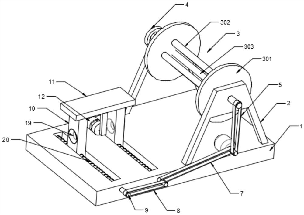
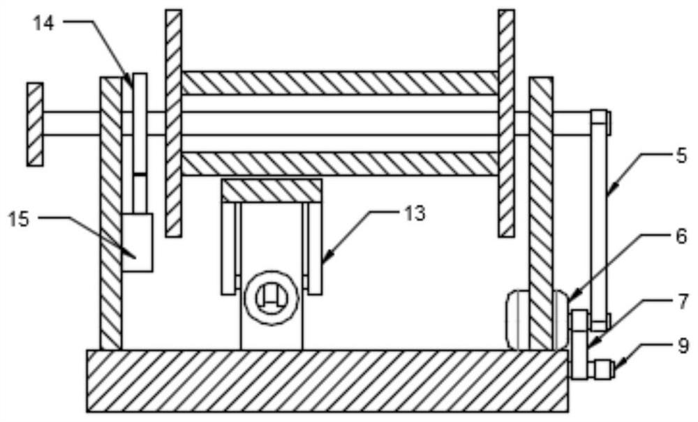
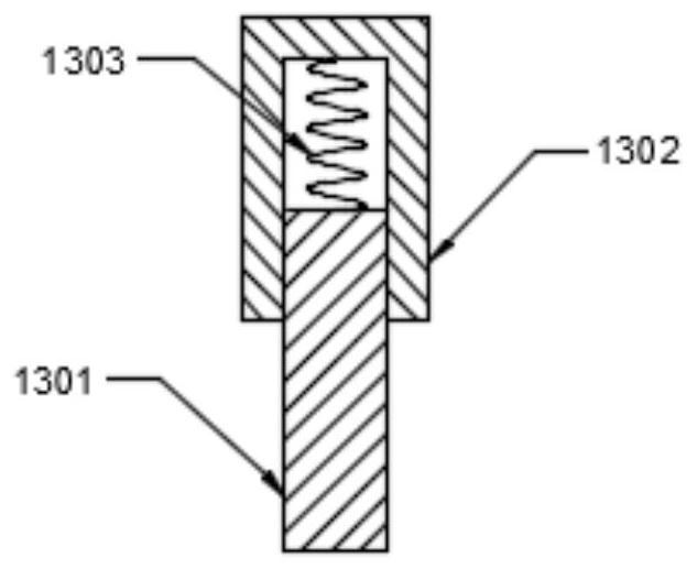
[0026] see Figure 1-4 , a wire take-up device for electric power, comprising a base 1, a support frame 2 is fixedly installed on both sides of the base 1, a wire roller assembly 3 is arranged between the two support frames 2, and a wire take-up adjustment assembly is arranged on the base 1, so The specific type of the wire-receiving adjustment assembly is not limited. In this embodiment, preferably, the wire-receiving adjustment assembly includes a slider 10, a mounting plate 11, a drum 12 and a fixing plate 13. The two sliders 10 are arranged on the base 1 and Both are provided with wire holes 19, and the mounting plate 11 is fixedly installed above the slider 10, and the two mounting plates 13 are symmetrically arranged at the lower end of the mounting plate 11, and the specific type of the mounting plate 13 is not limited. In this embodiment, the preferred , the fixed plate 13 includes a sleeve rod 1301, a sleeve 1302 and a connecting spring 1303, the sleeve 1302 is fixedl...

Embodiment 2

[0035] In order to improve the neatness of wire winding, this embodiment is further improved on the basis of Embodiment 1. The improvement is that: the base 1 is provided with a reciprocating assembly that drives two sliders 10 to reciprocate, and the reciprocating assembly The specific type is not limited. In this embodiment, preferably, the reciprocating assembly includes a second belt 7, a third belt 8, a reciprocating screw rod 9 and a chute 20. Two chute 20 are provided in the base 1 in parallel, and two The reciprocating screw mandrel 9 is rotatably installed in the two chutes 20 and one end extends to the outside of the base 1 and is driven and connected by the third belt 8. The second belt 7 is driven to connect the output end of the drive motor 6 with one of the reciprocating screw mandrels 9, and the two The sliders 10 are respectively slidably installed in the two slide grooves 20 and are threadedly connected with the reciprocating screw mandrel 9 .

[0036]In order...


PUM


Abstract

The invention discloses a take-up device for electric power. The take-up device comprises a base, wherein supporting frames are fixedly mounted on two sides of the base; a wire roller assembly is arranged between the two supporting frames; a take-up adjusting assembly is arranged on the base; the take-up adjusting assembly comprises slide blocks, a mounting plate, a roller and fixed plates; the two slide blocks are arranged on the base, and each of the two slide blocks is provided with a wire hole; the mounting plate is fixedly mounted above the slide blocks; the two fixed plates are symmetrically arranged at the lower end of the mounting plate; each fixed plate comprises a sleeve rod, a sleeve and a connecting spring; the sleeves are fixedly mounted on the mounting plate; each sleeve rodis movably arranged in the corresponding sleeve in a sleeving manner, and each connecting spring is arranged between the corresponding sleeve rod and the corresponding sleeve; the roller is rotatablymounted between the two sleeve rods; through arrangement of the take-up adjusting assembly, an electric wire on the wire roller assembly penetrates through the wire holes of the two slide blocks in atake-up process; and under the action of the connecting springs, the roller abuts against the electric wire all the time, so that the electric wire released from the wire holes is not loosened all thetime and is prevented from being knotted.

Description

technical field [0001] The invention relates to the field of electric power, in particular to a wire take-up device for electric power. Background technique [0002] With the increasing popularity of industrial and domestic electricity, the work of electric power construction and maintenance is becoming more and more heavy. Cable erection is the most common work in electric power construction. In the work, it is often necessary to rewind the wires. The existing winding device cannot adjust the tightness of the wires, which makes the wires easy to knot and inconvenient to use. Contents of the invention [0003] The object of the present invention is to provide a wire take-up device for electric power, so as to solve the problems raised in the above-mentioned background technology. [0004] To achieve the above object, the present invention provides the following technical solutions: [0005] A wire take-up device for electric power, comprising a base, support frames are f...

Claims


Application Information

Patent Timeline
IPC IPC(8): B65H54/28B65H57/22B65H54/38B65H54/70H02G1/02
CPCB65H54/2818B65H54/38B65H54/70B65H57/22B65H2701/34H02G1/02
Inventor 宋允华
Owner 宋允华
Why Eureka
Try Eureka