
Wire cutting device

A technology for cutting device and thread, applied in the directions of filament generation, transportation and packaging, artificial filament support, etc., can solve the problems such as obstruction of operation and difficulty of the thread guide, achieve miniaturization and cost reduction, realize cost reduction, Achieving the effect of miniaturization

Active Publication Date: 2016-04-20
TMT MACHINERY INC
View PDF11 Cites 0 Cited by
  • Summary
  • Abstract
  • Description
  • Claims
  • Application Information

AI Technical Summary

Problems solved by technology

[0007] In addition, in the conventionally proposed yarn cutting device, since the yarn guide (yarn guide plate) is arranged on the opposite side of the aspirator (suction device), when threading the yarn passage restricting guide, etc., there is the above-mentioned problem. When the yarn guide (yarn guide plate) becomes an obstacle and the work becomes difficult (for example, refer to Patent Document 1)

Method used


Image

  • Wire cutting device
  • Wire cutting device
  • Wire cutting device

Examples


Embodiment Construction

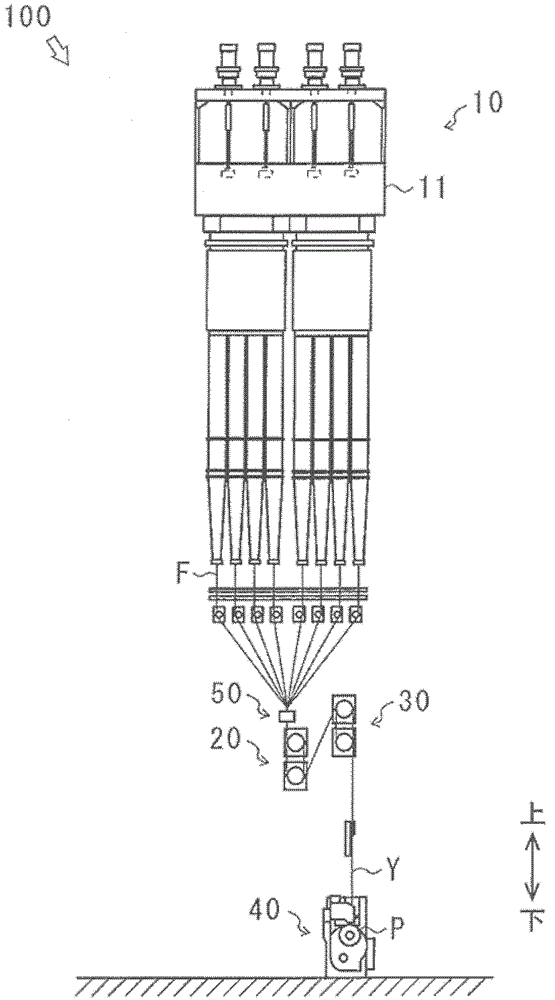
[0033] First, the spinning winding device 100 will be described.

[0034] figure 1 It is a figure which shows the structure of the spinning winding equipment 100. In addition, the acting direction of gravity is shown in the figure as an up-down direction.

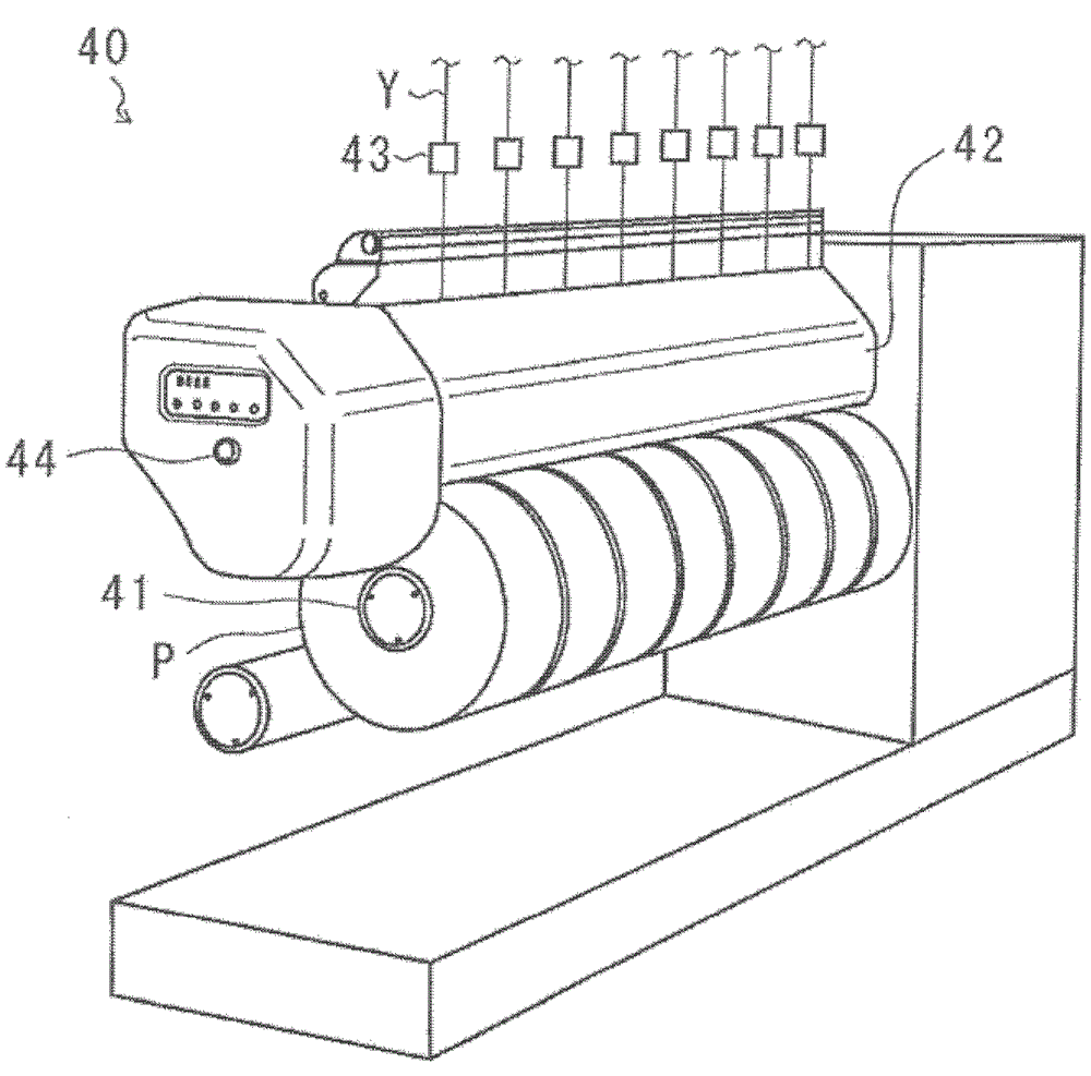
[0035] The spinning and winding facility 100 bundles a plurality of filaments F spun from the spinning device 10 to form a yarn Y, and processes the yarn Y such as stretching, and then winds it up to produce a package P. The spinning winding device 100 of this embodiment mainly includes a spinning device 10 , a first pair of godet rollers 20 , a second pair of godet rollers 30 , and a winding device 40 .

[0036] The spinning device 10 spins a plurality of filaments F. The spinning device 10 press-feeds the input synthetic fiber raw material (filament raw material) in a molten state, and spins it out from a spinning port provided on the spinning head 11 . In addition, the spinning device 10 is arranged at the uppermost ...


PUM


Abstract

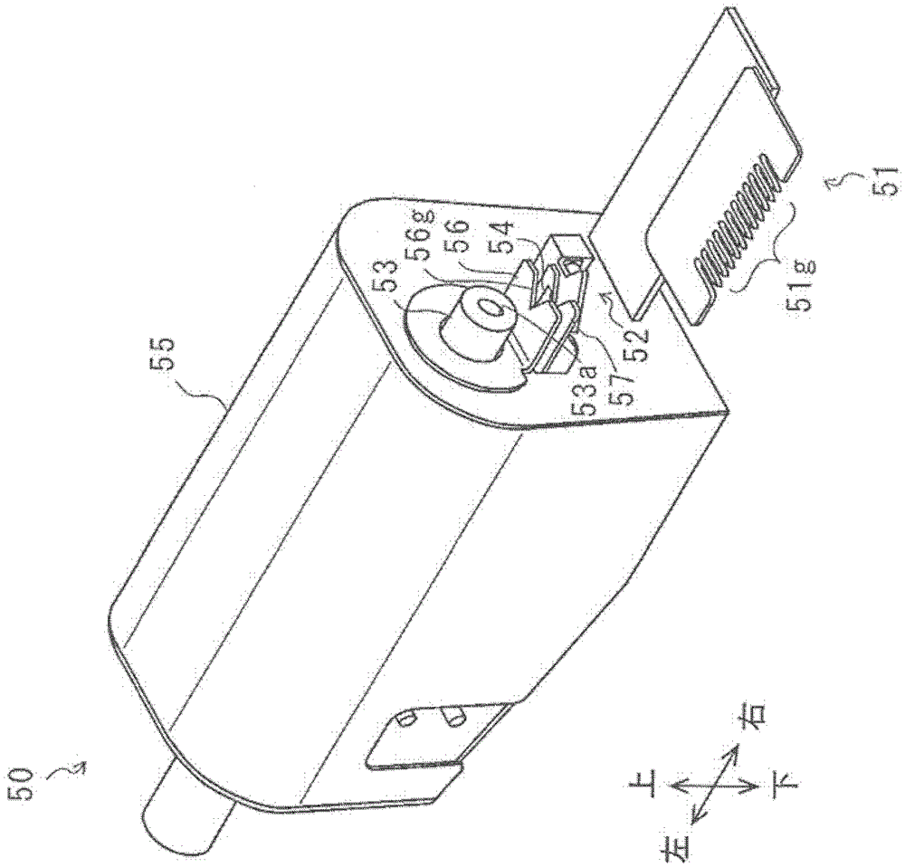
A yarn cutting apparatus is provided that improves the workability of the yarn threading operation while securely cutting a plurality of yarns. A yarn cutting apparatus (50) is configured to cut a plurality of yarns Y and includes a yarn path regulating guide (51) configured to guide the plurality of yarns Y, a yarn shift guide (52) disposed further upstream than the yarn path regulating guide (51) so as to shift the yarns Y fed onto the yarn path regulating guide (51) to one direction, an aspirator (53) disposed further upstream than the yarn shift guide (52) so as to suck the yarns Y shifted by the yarn shift guide, and a cutter (54) disposed between the yarn shift guide (52) and the aspirator (53) so as to cut the yarns Y sucked by the aspirator (53).

Description

technical field [0001] The present invention relates to the technology of a wire cutting device for cutting a wire. More specifically, it relates to a technology of a yarn cutting device that cuts a yarn produced in a spinning winding facility. Background technique [0002] Conventionally, there is known a spinning take-up device that bundles a plurality of filaments spun from a spinning device to form a yarn, and processes the yarn, such as drawing, and then winds the yarn to produce a package. [0003] In such spinning and winding equipment, when starting yarn production and winding, an operator needs to perform a so-called threading operation of hanging the filament or yarn on each roller or each guide. In addition, when an abnormality occurs such as the produced yarn being entangled on the roller, the yarn is cut and restored, so the operator needs to perform the threading operation again. [0004] However, the threading operation for hanging a plurality of filaments a...

Claims


Application Information

Patent Timeline
Patent Type & Authority Patents(China)
IPC IPC(8): D01D13/02D01D10/04D01D11/04
CPCB65H54/88B65H54/71B65H57/16B65H57/28B65H2701/3132
Inventor 桥本欣三岸根章典
Owner TMT MACHINERY INC
Learn More