[0007] 1. The tail rope monitoring device using the traditional single-rope detection and single-switch circuit monitoring technology has high faults, poor detection accuracy and low work efficiency
According to the statistics of previous tail rope switch failures in the main shaft of Meishan Iron Mine, the
failure rate of the tail rope switch is as high as 3 times per month. Every time a tail rope switch failure occurs, it must be
shut down immediately for
troubleshooting and maintenance. It is found that more than 95% of the tail rope failures are caused by The tail rope monitoring device malfunctions and false alarms are caused by external reasons and its own mechanism and
circuit failure. The detection rope, detection switch and circuit of the whole device are single and there is no replacement. Therefore, after each failure, the hoist trips and shuts down, which must be confirmed on site. can only be resumed after
processingBecause the maintenance personnel must go down to the underground level, and then
climb down the ladder to confirm and repair the tail rope device in the shaft bottom pit with a depth of tens of meters. The treatment after each failure is quite time-consuming, reaching more than 2 hours, which seriously affects The normal production of the raw ore of the hoist in the main shaft caused large economic losses
[0008] 2. Since the tail rope monitoring device is installed under the tail rope isolation frame, in the deepest part of the shaft of the hoisting mine, the depth from the
ground level is often hundreds of meters deep, and the site environment is very harsh. Climbing over the derrick to repair the
switchgear, a slight accident may cause a well
fall accident. In addition, the operation is difficult, and more than 3 people are required to cooperate with each inspection and repair
At the same time, due to the accumulation of ore in the hoisting shaft, falling rocks can easily cause casualties, which is a
Class III hazard source, resulting in frequent on-site handling of tail rope switch failures, resulting in increased safety risks
[0009] 3. The traditional tail rope monitoring device adopts single-rope detection and single-switch circuit monitoring technology. For false monitoring and alarms that do not actually cause kinks or broken ropes in the tail rope, it is unavoidable to confirm and eliminate the downhole site fault immediately at the first time.
[0010] 4. In the existing tail rope monitoring device, the detection rope mostly uses ordinary iron wire, which has the
disadvantage of being easy to
rust in a humid, acidic, and watery environment. After being in a humid environment for a long time and causing
corrosion, its
toughness,
hardness, elasticity, and
impact resistance are significantly reduced. And it is easy to break, so it often happens that the detection rope is broken, or it is rotten and broken, which leads to the failure of the tail rope monitoring device and false alarms to cause the hoist to stop due to failure, thus becoming a major shortcoming of the traditional tail rope monitoring device. Ordinary iron wire acts as a detection rope defect is obvious
Moreover, the external force required for its on-off is very small, as long as a slight external force is applied to tilt the
mercury switch, the mercury can move to make the switch realize on-off, so its sensitivity is too high
Using it as a tail rope detection switch can solve the problem of
corrosion resistance of the switch, but its glass shell is easily broken by the rocks falling from the bottom pit of the shaft. A slight shake may cause the
mercury switch to be turned on and off by mistake, which just becomes the biggest defect in use.
At the same time, it is found that the
mercury switch often leaks air after long-term use, and the quality is poor. The installation and debugging of the one-way mercury tilt switch applied to the tail rope switch is also troublesome, poor intuition, and the strong fluidity of mercury also makes the on-off position unfavorable. To be sure, repeated debugging is required, which increases the intensity and difficulty of maintenance work
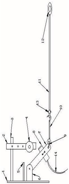
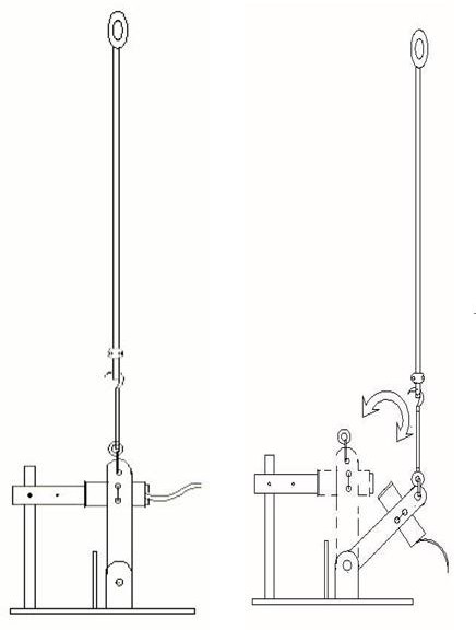
[0012] 6. The known traditional tail rope monitoring devices are relatively simple in installation and structure. Most of them are used to cross a detection rope in the tail rope loop under the tail rope isolation frame, and tie one end to the derrick after tightening and straightening. On the steel beam, the other end is connected with the bottom plate fixedly installed with the mercury switch, and then horizontally stretched and bound to the derrick steel beam on the other lateral side
Although this installation method and working structure seem simple, it is difficult to tighten the wire used for detection and fixing because the material of the binding wire is relatively hard. In fact, the detection rope cannot reach the ideal tension, so make debugging difficult
At the same time, after a long period of time, the iron wire is more stressed and deformed, causing the expected conduction angle of the mercury switch to change, resulting in a decline in
detection performance and a tail rope monitoring failure.

