Intelligent suction crane based on optical-mechanical-electrical integration technology

A suction crane, opto-electromechanical technology, applied in cranes and other directions, can solve the problems of poor positioning effect of the mounting frame, poor fixing effect of the suction crane, inconvenient adjustment of the angle of the beam, etc., and achieve the effect of increasing the fixing effect.

Inactive Publication Date: 2020-10-30
SHANDONG VOCATIONAL COLLEGE OF LIGHT IND
View PDF0 Cites 0 Cited by
  • Summary
  • Abstract
  • Description
  • Claims
  • Application Information

AI Technical Summary

Problems solved by technology

[0005] In order to solve the above-mentioned technical problems, the present invention provides an intelligent suction hoist based on optomechanical integration technology to solve the inconvenience of adjusting the angle of the beam in the existing suction hoist, the poor positioning effect of the mounting frame, and the suction hoist. The frame is easy to cause friction with the beam and the fixation effect of the suction hoist is poor when it is installed on the ground

Method used


Image

  • Intelligent suction crane based on optical-mechanical-electrical integration technology
  • Intelligent suction crane based on optical-mechanical-electrical integration technology
  • Intelligent suction crane based on optical-mechanical-electrical integration technology

Examples


Embodiment

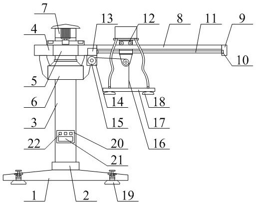
[0041] as attached figure 1 And attached figure 2 shown

[0042] The present invention provides an intelligent suction hoist based on optomechanical integration technology, which includes a fixed chassis 1, a bottom fixed chassis 2, a longitudinal bracket 3, a beam 4, a ball bearing 5, a reinforced bracket structure 6, and a top rotating frame structure 7. Rectangular bar 8, fixed seat 9, roller bearing 10, threaded rod 11, mobile hanger structure 12, rotating motor 13, winding motor 14, winding roller 15, steel wire sling 16, transverse plate 17, fixed sucker 18, can Adjust the fixed frame structure 19, the console 20, the controller 21 and the control button 22, the bottom fixed frame 2 is welded on the top of the fixed bottom frame 1; the longitudinal support 3 is welded on the top of the bottom fixed frame 2; The beam 4 described above is welded to the outer ring of the ball bearing 5; the inner ring of the ball bearing 5 is sleeved on the outer upper part of the longitud...


PUM


Abstract

The invention provides an intelligent suction crane based on an optical-mechanical-electrical integration technology. The intelligent suction crane comprises a fixed underframe, a bottom fixed frame,a longitudinal support, a cross beam, a ball bearing, a reinforced support structure, a top rotating frame structure, a rectangular cross rod, a fixed seat, a roller bearing, a threaded rod, a movablehanging frame structure, a rotating motor, a winding motor, a winding roller, a steel wire lifting rope, a transverse plate, fixed suckers, adjustable fixed frame structures, a control table, a controller and control buttons, wherein the bottom fixed frame is welded to the upper part of the fixed underframe. According to the intelligent suction crane, a driven gear is arranged on the upper part of the cross beam through bolts and is engaged with a driving gear so that the cross beam can rotate on the outer ring of the ball bearing, and the position angle of the cross beam can be convenientlyadjusted; and a positioning wheel shaft is connected to the inner side of a wheel frame through a shaft and is in contact with the outer wall of the longitudinal support, so that the positioning of the cross beam is facilitated, and the situation that normal use is affected due to the fact that the cross beam inclines to one side is avoided.

Description

technical field [0001] The invention belongs to the technical field of heavy machinery equipment, and in particular relates to an intelligent suction hoist based on optical-mechanical-electrical integration technology. Background technique [0002] Vacuum suction lifter (commonly known as elephant nose vacuum lifter) is a fast, safe and convenient automatic equipment. It uses the principle of vacuum adsorption to firmly suck up various workpieces, and transports the workpieces to the Whether you need to stack boxes, or load barrels onto trucks, or stack metal sheets or wood, or move stone or furniture, using a vacuum lifter is always the best handling solution . [0003] But existing suction hoist exists inconveniently to adjust the angle of crossbeam, and the positioning effect to installation frame is poor, and suction hanger easily produces friction with crossbeam and the problem that fixation effect is poor when suction hoist is installed on the ground. [0004] Theref...

Claims


Application Information

Patent Timeline
Patent Type & Authority Applications(China)
IPC IPC(8): B66C23/02B66C23/62B66C23/84
CPCB66C23/022B66C23/025B66C23/62B66C23/84
Inventor 邱明鑫
Owner SHANDONG VOCATIONAL COLLEGE OF LIGHT IND
Why Eureka
Try Eureka