Cantilever frame system

A suspension frame and I-beam technology, applied in the field of suspension frame system, can solve the problems of insufficient shock resistance and rust resistance, inconvenient installation and disassembly, etc.

Pending Publication Date: 2020-10-30
CONSTR COMPANY OF CHINA RAILWAY NO 8 ENGNEERING GRP +1
View PDF0 Cites 3 Cited by
  • Summary
  • Abstract
  • Description
  • Claims
  • Application Information

AI Technical Summary

Problems solved by technology

[0003] The purpose of the present invention is to provide a cantilever frame system for the above disadvantages, to solve the existing cantilever sys

Method used


Image

  • Cantilever frame system
  • Cantilever frame system
  • Cantilever frame system

Examples


Embodiment 1

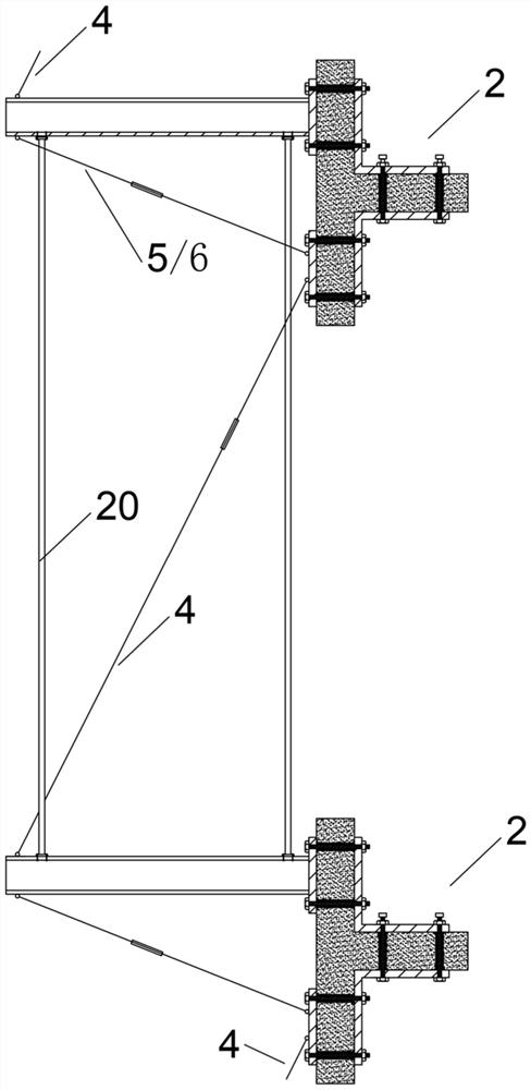
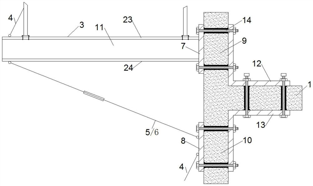
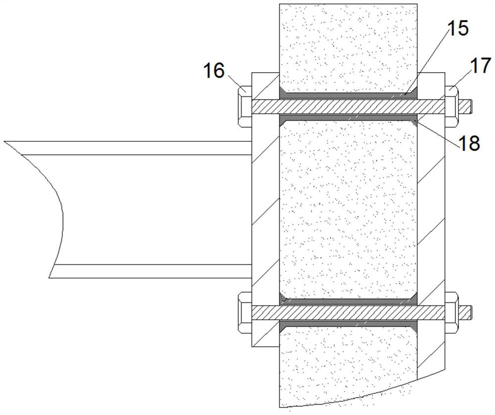
[0026] See attached Figure 1-7 . A cantilever frame system, including several cantilever frame assemblies 2 corresponding to the floor 1 one-to-one; , an upper seat 7 and a lower seat 8; the rear end of the I-beam 3 is provided with an upper seat 7; the upper seat 7 is fixed on the outside of the upper side wall 9 adjacent to the floor 1; the lower seat 8 is fixed on the adjacent wall 1 The outer side of the lower side wall 10; the two ends of the upper pull rod 4 are respectively connected to the I-beam 3 and the lower seat 8 of the cantilever frame assembly 2 above the corresponding cantilever frame assembly 2 of the I-beam 3, for giving the I-beam Steel 3 provides the pulling force on the upper rear; the two ends of the lower left support rod 5 and the lower right support rod 6 are respectively connected to the I-beam 3 and the lower seat 8; the lower left support rod 5 and the lower right support rod 6 are about the The vertical plate 11 of 3 is symmetrically arranged, ...

Embodiment 2

[0028] See attached Figure 1-7 . A cantilever frame system, including several cantilever frame assemblies 2 corresponding to the floor 1 one-to-one; , an upper seat 7 and a lower seat 8; the rear end of the I-beam 3 is provided with an upper seat 7; the upper seat 7 is fixed on the outside of the upper side wall 9 adjacent to the floor 1; the lower seat 8 is fixed on the adjacent wall 1 The outer side of the lower side wall 10; the two ends of the upper pull rod 4 are respectively connected to the I-beam 3 and the lower seat 8 of the cantilever frame assembly 2 above the corresponding cantilever frame assembly 2 of the I-beam 3, for giving the I-beam Steel 3 provides the pulling force on the upper rear; the two ends of the lower left support rod 5 and the lower right support rod 6 are respectively connected to the I-beam 3 and the lower seat 8; the lower left support rod 5 and the lower right support rod 6 are about the The vertical plate 11 of 3 is symmetrically arranged, ...

Embodiment 3

[0031] See attached Figure 1-7 . A cantilever frame system, including several cantilever frame assemblies 2 corresponding to the floor 1 one-to-one; , an upper seat 7 and a lower seat 8; the rear end of the I-beam 3 is provided with an upper seat 7; the upper seat 7 is fixed on the outside of the upper side wall 9 adjacent to the floor 1; the lower seat 8 is fixed on the adjacent wall 1 The outer side of the lower side wall 10; the two ends of the upper pull rod 4 are respectively connected to the I-beam 3 and the lower seat 8 of the cantilever frame assembly 2 above the corresponding cantilever frame assembly 2 of the I-beam 3, for giving the I-beam Steel 3 provides the pulling force on the upper rear; the two ends of the lower left support rod 5 and the lower right support rod 6 are respectively connected to the I-beam 3 and the lower seat 8; the lower left support rod 5 and the lower right support rod 6 are about the The vertical plate 11 of 3 is symmetrically arranged, ...


PUM


Abstract

The invention discloses a cantilever frame system, and belongs to the technical field of building operations. The cantilever frame system comprises a plurality of cantilever frame components. The rearend of I-steel of each cantilever frame component is provided with an upper base. The upper base is fixed to the outside of an upper side wall. Lower base is fixed to the outside of an lower side wall. The two end of a upper pulling rod is respectively connected with the I-steel and the lower base of the cantilever frame component, and the lower base is arranged above the cantilever frame component corresponding to the I-steel, and is used for providing the rear upper tension to the I-steel. The two ends of a left lower supporting rod and a right lower supporting rod are respectively connected with the I-steel and the lower base. The left lower supporting rod and the right lower supporting rod are symmetrically arranged on a vertical plate of the I-steel. The intersection of the extensionlines the left lower supporting rod and the right lower supporting rod is located on the upward extending surface of the vertical plate the I-steel. According to the cantilever frame system, the I-steel is more stable and reliable to perform fixing with multiple stress support and safety protection, is easy to install and disassemble, and has a certain seismic capacity and rust-resistant performance.

Description

technical field [0001] The invention belongs to the technical field of building construction, and in particular relates to a suspension frame system. Background technique [0002] In the construction process of the construction project, in order to set up scaffolding on the outside of the building, it is necessary to set a large number of I-beams on the outer wall as support for erection. But there are many problems in the cantilever frame system with I-beam as the main component at present. When most of the I-beams are installed on the exterior wall of the building, the I-beam penetrates the exterior wall, the part of the I-beam in the interior is fixed on the floor, and the protruding part is used as a scaffolding support, which not only causes The destruction of the wall caused safety hazards and wasted a lot of steel. Many dismantling of I-beams is destructive and cannot be completely recycled. The I-beam is generally used with a pull-up rod. The pull-up rod is used t...

Claims


Application Information

Patent Timeline
IPC IPC(8): E04G5/04E04G3/20E04B1/64E04B1/92E04B1/98E04H9/02
CPCE04B1/642E04B1/92E04B1/98E04G3/20E04G5/046E04H9/02
Inventor 林海陈胜雷中平彭舸田建伟覃先壮傅鹏冉华郑学军熊进龙冉立
Owner CONSTR COMPANY OF CHINA RAILWAY NO 8 ENGNEERING GRP
Why Eureka
Try Eureka