
Electromechanical coupling buffer device of range extender

A technology of electromechanical coupling and buffering devices, applied in clutches, shaft couplings, mechanical equipment, etc., can solve problems such as spline breakage, lowering, and easy to generate impact noise

Inactive Publication Date: 2020-10-30
DONGFENG LIUZHOU MOTOR
View PDF13 Cites 1 Cited by
  • Summary
  • Abstract
  • Description
  • Claims
  • Application Information

AI Technical Summary

Problems solved by technology

[0004] The purpose of the present invention is to overcome the deficiencies of the prior art and provide a range extender electromechanical coupling buffer device to solve the technical problem: the range extender in the prior art is prone to produce a Impact noise, easy to cause related bolts, spline breakage and reduce the service life of crankshaft and crankshaft

Method used


Image

  • Electromechanical coupling buffer device of range extender
  • Electromechanical coupling buffer device of range extender
  • Electromechanical coupling buffer device of range extender

Examples


Embodiment Construction

[0038] The specific implementation manners of the present invention will be further described in detail below in conjunction with the accompanying drawings and embodiments. The following examples are used to illustrate the present invention, but are not intended to limit the scope of the present invention.

[0039] In the description of the present invention, it should be understood that the orientation or positional relationship indicated by the terms "upper", "lower", "left", "right", "top", "bottom" etc. Orientation or positional relationship is only for the convenience of describing the present invention and simplifying the description, and does not indicate or imply that the referred device or element must have a specific orientation, be constructed and operated in a specific orientation, and thus should not be construed as a limitation of the present invention. It should be understood that the terms "first", "second", etc. are used in the present invention to describe va...


PUM


Abstract

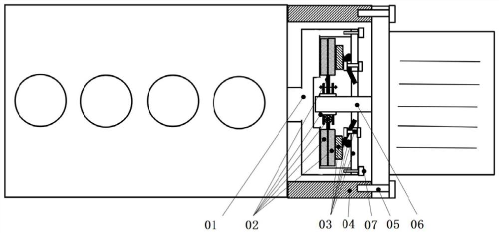
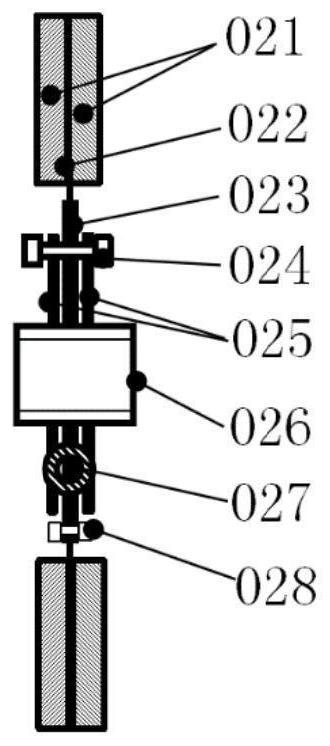
The invention discloses an electromechanical coupling buffer device of a range extender. The electromechanical coupling buffer device is used for connecting an engine flywheel and a generator spline shaft; and the device comprises a shell, a friction plate assembly and a pressure plate assembly; the engine flywheel is inserted into the shell; the friction plate assembly is arranged in a gear ringof the engine flywheel in a matched mode; a friction plate is pressed in the middle of the pressing disc assembly in a matched mode, and the edge of the pressing disc assembly is connected with the gear ring; and the generator spline shaft sequentially penetrates through the pressing plate assembly and the friction plate assembly in a matched mode, and the shell is connected with an engine. The electromechanical coupling buffer device of the range extender buffers vibration between the engine flywheel and the generator spline shaft, noise caused by impact generated by an engine and a generatorduring variable-working-condition operation is avoided, and the situation that the service life of an engine crankshaft and the service life of a crankshaft bush are affected due to the fact that theengine crankshaft and the engine crankshaft bush are subjected to large alternating loads is avoided; and meanwhile, fracture failure of bolts and splines caused by impact load is avoided.

Description

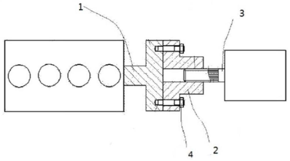
technical field [0001] The invention relates to the technical field of automobiles, in particular to an electromechanical coupling buffer device for a range extender. Background technique [0002] The coupling structure between the engine and the generator in the prior art is generally a non-buffer mechanism, such as figure 1 As shown, the engine flywheel 1 and the connection plate 2 are fixedly connected by the connection plate bolts 4. At the same time, the generator shaft spline 3 is inserted in the connection plate 2. This coupling structure has no buffer mechanism, resulting in the engine running under variable conditions. There is an impact with the generator, which produces a large noise and affects the driving experience; when the operating conditions are variable, it is easy to cause the engine crankshaft and bearing bush to be subjected to large alternating loads, which will affect the service life of the crankshaft and crank bush; fasten the connecting plate. Bol...

Claims


Application Information

Patent Timeline
Patent Type & Authority Applications(China)
IPC IPC(8): F16D7/02F16D43/21F16F15/127
CPCF16D7/025F16D43/215F16F15/127
Inventor 邓发平赵明祥何道明潘永亮姚克甫
Owner DONGFENG LIUZHOU MOTOR
Learn More