
Refrigerator

A refrigerator and fin technology, applied in the field of refrigerators, can solve the problems of low defrosting efficiency, difficult installation, and relatively high installation angle requirements.

Pending Publication Date: 2020-10-30
HISENSE(SHANDONG)REFRIGERATOR CO LTD
View PDF6 Cites 1 Cited by
  • Summary
  • Abstract
  • Description
  • Claims
  • Application Information

AI Technical Summary

Problems solved by technology

The first type: a shielding plate is installed on the heating wire. In order to ensure the defrosting efficiency, there are long holes on the shielding plate to facilitate the circulation of heat and reduce the probability of defrosting water dripping on the heating wire; the second type: heating wire Aluminum tube heating wire is used, which is evenly distributed between the evaporator tube and the fins. The temperature of the heating wire during the defrosting period will not exceed 90°C; these two methods can reduce or avoid abnormal noise during the defrosting period, but the first method is difficult to install , the position and installation angle of the shielding plate are relatively high; in the second method, since the heating wire is far away from the defrosting water tank, in order to ensure the smooth discharge of the defrosting water, it is necessary to add a heating wire to the defrosting water tank, and it takes a long time Defrost, so the defrosting efficiency of the whole machine is very low, which is not conducive to the freezing performance of the refrigerator

Method used


Image

  • Refrigerator
  • Refrigerator
  • Refrigerator

Examples


Embodiment Construction

[0032] In order to make the object, technical solution and advantages of the present invention clearer, the present invention will be further described in detail below in conjunction with the accompanying drawings and embodiments.

[0033] It should be noted that, in the description of the present invention, the terms "up", "down", "left", "right", "vertical", "horizontal", "inner", "outer" and the like indicate directions or positions The terms of the relationship are based on the orientation or positional relationship shown in the drawings, which are for convenience of description only, and do not indicate or imply that the device or element must have a specific orientation, be constructed and operated in a specific orientation, and therefore cannot be interpreted as Limitations on the Invention. In addition, the terms "first" and "second" are used for descriptive purposes only, and should not be understood as indicating or implying relative importance.

[0034] refer to ...


PUM


Abstract

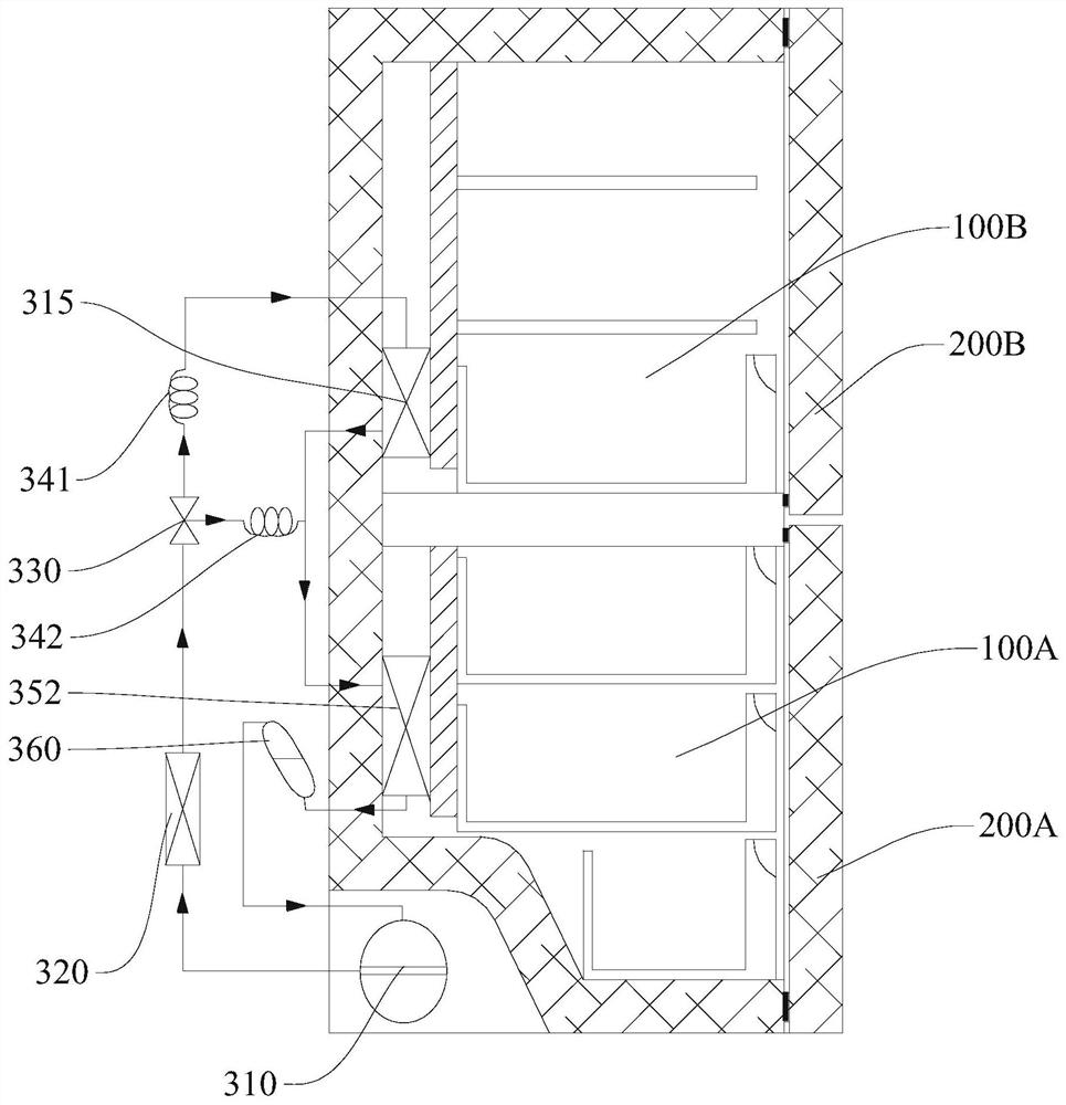
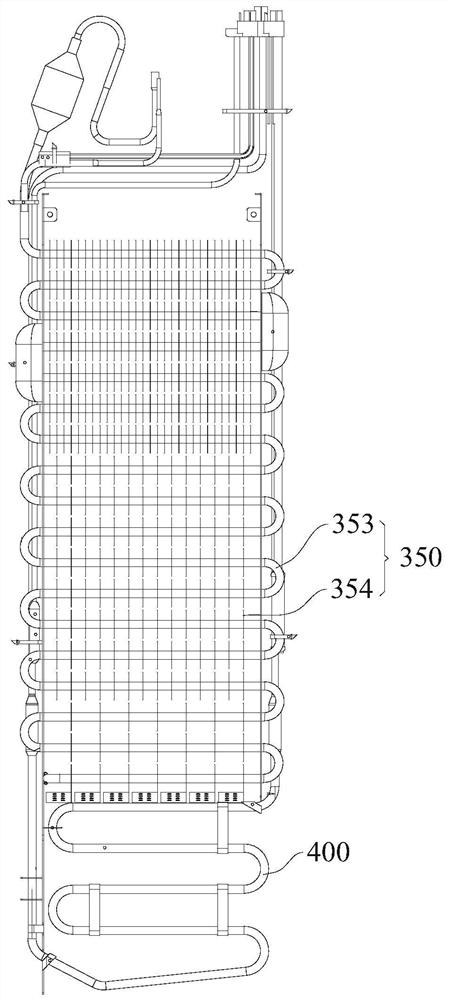
The invention discloses a refrigerator. The refrigerator comprises a storage chamber and an evaporator chamber located on the lower side of the interior of the storage chamber. The evaporator chambercomprises an evaporator and a heater. A water catcher is arranged at the bottom of the evaporator chamber. The evaporator comprises a coiled pipe and a plurality of rows of fins sleeved on the coiledpipe. The bottom edges of the row of the fins on the bottommost side are bent to form bending parts. The heater is arranged below the bending parts. The bending parts are provided with ventilation parts. Defrosting water generated by the evaporator does not pass through the heater along at least one ends of the bending parts and directly flows into the water catcher. According to the refrigerator,the bending parts of the fins form a blocking plate structure, the blocking plate structure guides defrosting water into the water catcher from at least one side of the bending parts, prevents defrosting water from dripping onto a heating wire and causing abnormal noise and can also prevent ice blocks from falling off during the defrosting period and prevent the situation that the ice blocks falloff, are vaporized speedily and generates noise. The refrigerator is simple in overall structure. There is no need to additionally arranged other shielding components between the evaporator and the heater. The refrigerator is not limited by the installation space of the evaporator. The heater is located at the bottom of the evaporator, and the defrosting efficiency is high.

Description

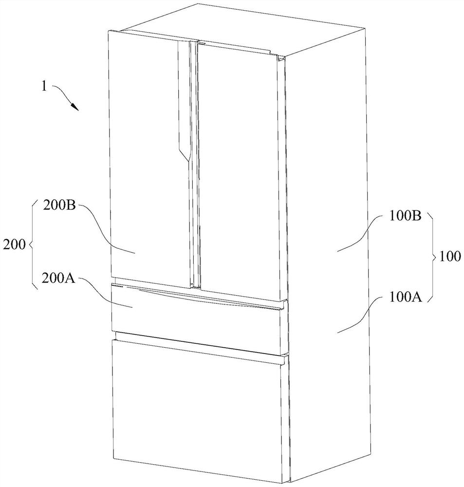
technical field [0001] The invention relates to the technical field of refrigeration equipment, in particular to a refrigerator. Background technique [0002] The defrosting principle of the refrigerator: the finned evaporator is fixed on the refrigerated liner, and the refrigerator cools so that frost forms on the finned evaporator. The frost water drops into the lower defrosting water receiving tank, flows into the evaporating pan outside the box through the drain pipe, and then passes through the hot pipeline in the evaporating pan to speed up the evaporation of the defrosting water. During the defrosting process, the temperature of the heating wire can reach over 300°C, and when the defrosting water or ice cubes drop onto the heating wire, they will be vaporized rapidly, producing a "squeaky" noise. [0003] There are two methods currently used to eliminate abnormal noise during defrosting, one is to shield the heating wire, and the other is to use low temperature (not ...

Claims


Application Information

Patent Timeline
Patent Type & Authority Applications(China)
IPC IPC(8): F25D11/02F25D21/06
CPCF25D11/02F25D21/06F25D2321/141
Inventor 张海鹏潘毅广丁龙辉孙敬龙
Owner HISENSE(SHANDONG)REFRIGERATOR CO LTD
Learn More