
Planning method of prepreg tape laying track based on specified geodesic curvature

A technology of laying trajectory and geodesic curvature, which is applied in the direction of instruments, digital control, control/regulation systems, etc., and can solve problems such as large calculation errors and large gaps between prepreg tapes

Active Publication Date: 2020-10-30
CHANGSHA UNIVERSITY OF SCIENCE AND TECHNOLOGY
View PDF10 Cites 1 Cited by
  • Summary
  • Abstract
  • Description
  • Claims
  • Application Information

AI Technical Summary

Problems solved by technology

Zhang Peng (A geometric method for computation of geodesic on parametric surfaces. Computer Aided Geometric Design, 2015,38:24-37.) proposed a geometric method for computation of geodesic on parametric surfaces, but the method only has a first-order Accuracy, the calculation error on the complex surface is large, it is easy to cause the gap between the final prepreg tapes to be too large or too small

Method used


Image

  • Planning method of prepreg tape laying track based on specified geodesic curvature
  • Planning method of prepreg tape laying track based on specified geodesic curvature
  • Planning method of prepreg tape laying track based on specified geodesic curvature

Examples


Embodiment 1

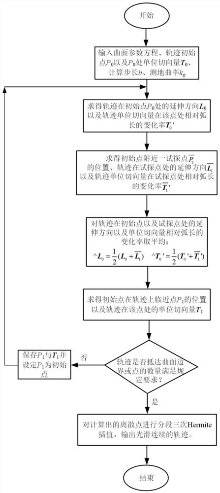
[0030] Such as figure 1 As shown, a planning method for prepreg tape laying trajectory based on prescribed geodesic curvature includes the following steps:

[0031] S1. Input the three-dimensional model of the mold surface to be laid, the initial point P of the laying track of the prepreg tape 0 The location of the prepreg tape laying track at the initial point P 0 The unit tangent vector T at 0 , calculation step size h, specified geodesic curvature value k g ;

[0032] S2. According to the unit tangent vector T in step S1 0 Get the prepreg tape laying trajectory at the initial point P 0 The extension direction L at 0 ;According to the specified geodesic curvature value k g Compute the unit tangent vector T 0 at the initial point P 0 relative arc length change rate T 0 ';

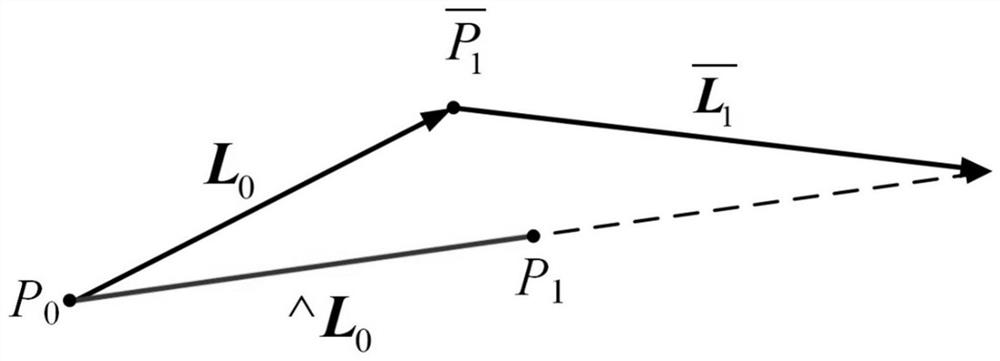
[0033] S3. According to the initial point P in step S1 0 The position of , the calculation step size h, and the extension direction L in step S2 0 , get the tentative point According to the ...

Embodiment 2

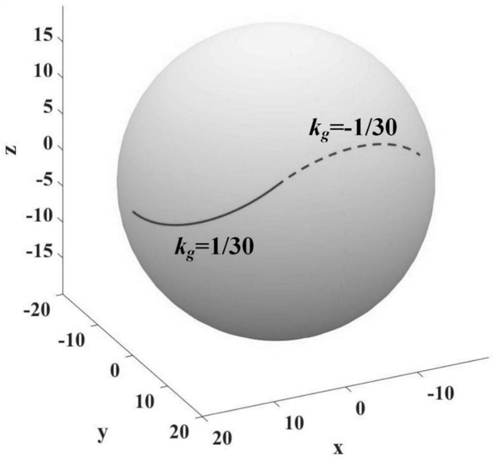
[0053] In this embodiment, the spherical surface is used as the parametric surface of the mold to be laid, and the specific process is as follows:

[0054] S1. Input the spherical parameter equation r(u,v)=[20cos(u)cos(v), 20sin(u)cos(v), 20sin(v)], the initial point P of the prepreg tape laying track 0 =(0,0) is located on the spherical surface, and the laying track of the prepreg tape is at the initial point P 0 The unit tangent vector T at 0 =[0,1,0]; input calculation step size h=1 and geodesic curvature k g distribution along the track

[0055] S2. Obtain the laying track of the prepreg tape at the initial point P 0 The extension direction L at 0 and the unit tangent vector T of the prepreg tape laying trajectory 0 at P 0 The change rate T of the relative arc length at 0 ’, the specific steps include:

[0056] (2.1) The unit tangent vector T on the three-dimensional model 0 Inversely mapped to the parameter surface of the mold surface to be laid to obtain the l...


PUM


Abstract

The invention discloses a planning method for a prepreg tape laying track based on a specified geodesic curvature. The planning method comprises the following steps: inputting a three-dimensional model of a curved surface of a to-be-laid mold, the position of an initial point P0 of the prepreg tape laying track, a unit tangent vector T0 of the prepreg tape laying track at the initial point P0, a calculation step length h and a specified geodesic curvature value kg; calculating extension directions and relative arc length change rates of the initial point and the test point; the method comprises the following steps of: obtaining an initial point P0, averaging the initial point P0, then obtaining an adjacent point P1 of the initial point P0, replacing the initial point P0 with the adjacent point P1, repeating the steps to obtain subsequent discrete points, and performing Hermite interpolation on the discrete points for three times in sections to generate a smooth and continuous prepreg tape laying track based on the specified geodesic curvature. The method disclosed by the invention can be applied to a non-developable curved surface, and the precision of trajectory planning is ensured.

Description

technical field [0001] The invention relates to the technical field of prepreg tape laying, in particular to a planning method for prepreg tape laying track based on specified geodesic curvature. [0002] technical background [0003] Automatic tape laying technology is a typical representative of composite material forming automation, and it is an important way to realize "low cost, high performance, high efficiency" manufacturing of composite materials, and it is widely used in the manufacture of aerospace high performance composite material structures. Trajectory planning is a key link in automatic tape laying technology, which directly affects the accuracy and efficiency of the laying process and the quality of the final product. The automatic tape laying trajectory planning has the following requirements: 1. Ensure that the wrinkles or stretches produced by a single tape are as small as possible; 2. Ensure that two adjacent tapes do not overlap and meet certain gap requi...

Claims


Application Information

Patent Timeline
IPC IPC(8): G05B19/4103
CPCG05B19/4103G05B2219/35187
Inventor 张鹏黄龙尹来容
Owner CHANGSHA UNIVERSITY OF SCIENCE AND TECHNOLOGY
Learn More